Home
Welcome to this mini course unit on the topic of virtualisation. Please use the menu of the left to access the different chapters of the unit, as well as the lab exercise.
Instructor: Pierre Olivier
Logistics
The slides for this chapter are available here.
Website
All the lecture materials including slides and lecture notes, as well as the lab exercise, are available online: https://olivierpierre.github.io/virt-101.
Outline
This unit is divided into chapters covering the following topics:
- Introduction to Virtualisation (~1h)
- Operating Systems Basics (~1h)
- The Theory of Virtualisation (~1h)
- Hardware Support for Virtualisation: CPU and Memory (~1h)
- I/O Virtualisation (~1h)
- Lightweight Virtualisation: Containers & Unikernels (~1h)
- Lab Exercise: Virtualising a Simple I/O Device (~2h)
Lab Exercise
We will conclude the day with a lab exercise in which we will virtualise a simple I/O device: a random number generator. Given the device specs, the goal of the exercise will be to implement its behaviour in software in the Qemu virtual machine monitor. That will involve building a driver in the guest (Linux) kernel, and running a VM with an application accessing the device through the driver. You will be given 2 weeks to complete that exercise, with a deadline set for 20/01/2026 (January 20, 2026). The exercise will be marked out of 20.
To complete the lab exercise you will be given remote (SSH) access to a Debian-based development environment. You can also use your personal machine if you have the proper software environment and hardware resources: a Debian or a Debian derivative (e.g. Ubuntu, Mint, etc.) with KVM support and 20 GB of storage free. It can be either natively installed on your personal machine, or running in a VM (e.g. VirtualBox, an image will be provided).
You can find more information about the exercise and its logistic on the corresponding part accessible from the left menu.
Reading List
The course unit is self-contained and in absolute you do not need to read any additional book to complete it. Still, a highly recommended book is:
Hardware and Software Support for Virtualization by Edouard Bugnion, Jason Nieh and Dan Tsafrir, Morgan & Claypool, 2017
This course unit is partially based on this book, which will be referred to as the textbook here.
A few other interesting books:
- The Definitive Guide to the Xen Hypervisor. David Chisnall, Pearson Education, 2008
- Modern Operating Systems, Andrew Tannenbaum and Herbert Bos, Prentice Hall Press, 2014
- Principles of Computer System Design: an Introduction, Jerome Saltzer and Frans Kaashoek, Morgan Kaufmann, 2009
- Linux Kernel Development, Robert Love, Addison-Wesley Professional, 2010
Introduction
The slides for this chapter are available here.
Definition
Let’s start with a quick and easy definition for the concept of virtualisation. It’s not really complete, but it is a simple starting point:
Virtualisation technologies are the set of software and hardware components that allow running multiple operating systems at the same time on the same physical machine
The type of virtualisation we’ll discuss in this unit mostly concerns the goal of running several operating systems (OSes) on the same physical machine. A fundamental challenge here is that by design an operating system expects to be the only privileged entity with total control over the hardware on a computer. In other words an operating system is not design to run alongside and share a machine with other operating systems. In that context, how can 2 or more OSes cohabit on a single machine?
To address that problem we use a combination of hardware and software to create a series of virtual machines (VMs) running on a given physical machine, and we run each operating system within its own VM. That way we give the illusion to each OS that it is running alone and in total control on its VM:

For this approach to work, the virtualisation layer needs to achieve 3 fundamental high-level objectives, illustrated below:
- The speed of an OS should be the same when running in a VM vs. running natively. Same thing for the user space applications running on top of that OS.
- The code of an existing OS supporting native execution should not have to be updated to run virtualised. Same thing for the applications.
- The OSes running virtualised on a physical machine should not be able to interfere with each others. For example they should not be able to access each other’s memory. A virtualised OS should not be able to bottleneck resources such as CPU, memory or I/O at the expense of the other virtualised OSes running alongside it.

Points 1 and 2 above are necessary for adoption: businesses are unlikely to adopt virtualisation solution if the performance hit is too high, or if it means changing OSes/application which is a significant engineering effort. Point 3 relates to security: virtualised OSes running on the same physical machine are often controlled by distrusting parties, and the virtualisation layer must enforce isolation guarantees.
A Bit of History
In the 1960s IBM produced System/360 (S/360), a family of computers of various sizes (i.e. processing power) built using the same architecture. A client could buy a small model for testing/prototyping, and a large mainframe later. Following that model, clients often realised they wanted to take a set of software application running on multiple small models and run them all on a single large model. This is called consolidation, and it is one of the main use cases for virtualisation.
14 models were produced between 1965 and 1978. The model 67 introduced a virtualisable architecture: a physical machine of that model could appear as a set of multiple, less powerful versions of itself: virtual machines (VMs).
In 1974 a seminal paper on the topic of virtualisation was published: Formal Requirements for Virtualizable Third Generation Architectures.
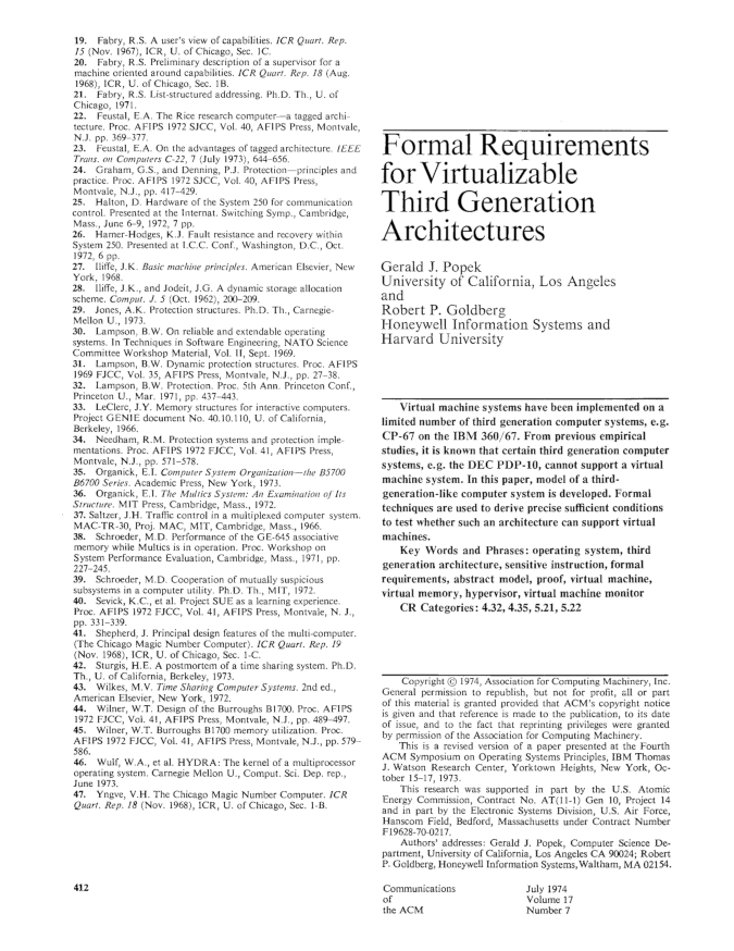
This paper, co-authored by computer scientists Gerald J. Popek and Robert P. Goldberg, listed the requirements for an Instruction Set Architecture (ISA) to be virtualisable. It also described the properties that the systems software managing virtual machines (the virtual machine monitor or the hypervisor) must have for virtualisation to be possible on that ISA. We will study that paper in details in one of the next lectures. Indeed, the principles defined in this article are still relevant today, and they have guided the design of modern virtualisable ISAs such as Intel/AMD x86-64, ARM64, or RISC-V.
At the time the Popek and Goldberg paper was published virtualisation was not in high demand. In the 1990s and early 2000s that changed. A growing need for virtualisation was motivated by various factors: the rising need for workload consolidation, the continuous increase in computing power, or the boom of data centres during the dot-com bubble. The problem was that the most widespread ISA at the time, Intel x86-32, was not properly virtualisable based on the requirements listed in the Popek and Goldberg paper. At that time several software-based virtualisation solution trying to virtualise x86-32 by overcoming the ISA’s limitations came out of academic research: Disco from Stanford, and Xen from Cambridge. These solutions later transitioned to the industry: the authors of Disco founded VMware, and Xen was for a long time the main virtual machine monitor used by Amazon Web Services.
In the 2000s the demand for virtualisation exploded. The modern ISAs that we still used today were designed with virtualisation in mind, following the principles defined by Popek and Goldberg. These ISAs include hardware support for virtualisation, which is leveraged by today’s virtual machine monitors such as Linux’s KVM, VirtualBox, Microsoft’s Hyper-V, or the current versions of Xen or KVM.
Use Cases
Consolidation
Consolidation consists in taking a set of software applications, e.g. a web server, a mail server, and other software, initially running on X physical machines, and running everything on a smaller set of Y physical machines (Y < X), possibly 1 by creating X virtual machines.

As previously mentioned, this is the historical motivation for developing virtualisation technologies.
Consolidation gives most of the benefits of multi-computer systems without the associated financial and management costs. The financial savings are clear: we need to buy less computers. The management savings include saving space and reducing the workload for system administrators by having fewer machines.
The benefits of multi-computer systems that can be maintained on a single or small set of machine(s) include:
- Heterogeneity of software dependencies: if we have several applications with different dependency needs in terms of operating system/library models and versions, it is easy to run each application within its own virtual machine set up with the proper environment for that particular application. Environments from different virtual machines don’t need to interfere with each others, and can evolve independently along with the needs in terms of dependency updates.
- Reliability: if one application crashes the system through a bug/resource hog, the fault will be contained within the containing VM and will not affect other virtual machines running on the same host.
- Security: same as for reliability, if one application gets hacked and the attacker manages to take over the operating system, the attack will still be confined to the containing VM and the attacker won’t be able to access other VMs running on the same host.
Software Development
Virtualisation offers significant advantages for software development by enabling multiple VMs to run on a single physical host, each with its own operating system and system libraries. This flexibility allows developers to emulate diverse environments without the need for multiple physical machines. For example, a developer working on a Windows machine but developing software for the Linux kernel features can use a VM to run different Linux distributions on the same host, ensuring compatibility and testing across versions.
Provisioning VMs is rapid and cost-efficient compared to setting up physical hardware, making it ideal for iterative development and continuous integration workflows. Furthermore, VMs are self-contained units that encapsulate the entire software stack including the operating system, libraries, and dependencies: they provide a reliable and reproducible environment for development, automated testing, and even deployment. This isolation reduces configuration conflicts and simplifies collaboration across teams.
These are the logos of a few technologies that are extensively used in software development:

- VirtualBox and VMware Workstation can run a Linux VM on a Windows host for Linux development without the need to install Linux natively.
- Vagrant allows automating the provisioning (installation) of one or several VMs for quick iterations of the development/testing/deployment cycle.
- Docker create containers that are VM-like environments that can be set up automatically and almost instantaneously. We’ll talk more about containers later in this course unit.
Migration, Checkpoint/Restart
The state of a running VM is easily identifiable, hence it is relatively simple to checkpoint/restart and live-migrate that VM.
Checkpoint/restart consist in taking a snapshot of the VM’s state and store it on disk. That snapshot can then be restored later for the VM to resume in the exact same state it was when the snapshot was taken. This is useful when executing long-running jobs (e.g. HPC applications, ML training, etc.): their progress can be saved with this technique to avoid restarting the entire job in case something goes wrong during their execution (e.g. crash).
Live migration consists in moving a VM from one physical host to another transparently, i.e. without tenants using the VMs noticing it: there should be no need for reconnecting and no noticeable performance drop during the migration. This is useful in many scenarios, e.g., to free resources for maintenance, power saving, load balancing, or when a fault is expected.
Both checkpoint/restart and live-migration are straightforward to realise with a VM. This is in opposition to checkpointing/migrating an application/a process, which is more complicated because the state of an application is made of many elements (including a lot of kernel data structures) that are hard to properly identify.
This seminal paper on VM live migration is worth a read: Clark et al., Live Migration of Virtual Machines, NSDI’05.
Hardware Emulation
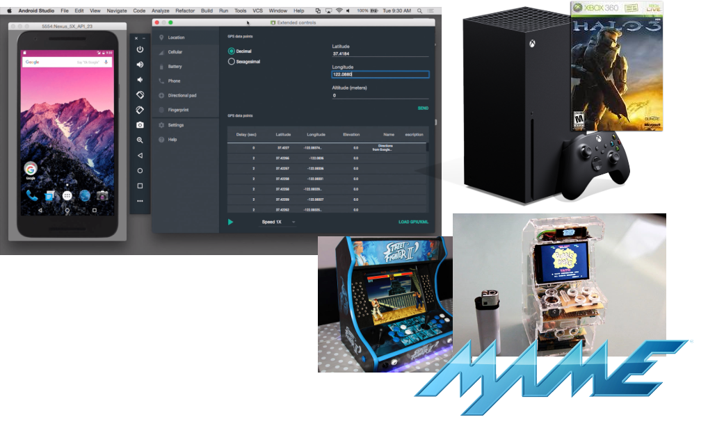
Emulation allows creating virtual machines which CPU has an architecture (ISA) that is different from that of the host computer. This is useful for software development or to provide backward compatibility. A few examples are illustrated below. The development frameworks for smartphones applications (iOS/Android) are generally used on standard desktop/laptop machines likely running Intel x86-64 CPUs, and allow for testing to create virtual machines representing smartphones that generally embed ARM64 CPUs. Modern video game consoles provide some degree of retro-compatibility with previous generations, for example the Xbox Series X released in 2020 can run XBOX 360 games that came out starting 2005. Emulation can also let users create on modern hardware virtual machines for hardware that is not widely available anymore, e.g. old arcade machines.
Cloud Computing
Virtualisation enables cloud computing, a computing paradigm in which cloud providers own a large amount of computing resources (server farms) provide remote access to these resources to their clients, named tenants. This allows tenants to offload local computing workloads to the provider’s infrastructure. Tenants share access to the provider’s resources, and it is common for multiple clients of a cloud provider to execute their workload on the same physical host. Because as a general rules tenants do not trust each other, it is very important for the resource sharing enabled by the cloud to be secure: the entire cloud business model relies on the proper isolation between tenants’ workloads. Imagine if there was no such isolation between two distrusting clients which workloads are co-located on the same host. One of these clients may be able to read and or modify the code/data related to the other’s workload, which would negate most of the benefits of cloud computing.
This strong isolation require between tenants’ workloads is achieved by placing their application in separate virtual machines. As we will see net, security/strong isolation between VMs is one of the design principles of virtualisation.
There are several ways for clients to leverage the cloud:
- Infrastructure as a Service (Iaas), in which clients rent VMs running on the provider’s infrastructure to run their workloads, e.g. a web server.
- Platform as a Service (PaaS), in which tenants develop and deploy their own applications using dedicated cloud frameworks, e.g., Google App Engine.
- Software as a Service (SaaS), where clients replace a commonly-used local service (e.g. an internal web server) with the cloud provider’s solution, e.g. using Gmail or Outlook 365 for emails.
- Function as a Service (FaaS), a newer paradigm in which developers deploy on the provider’s infrastructure individual functions that run on demand and automatically scale without managing servers.
The goals and benefits of cloud computing is for the tenants to save on management, infrastructure, development, maintenance costs. Below are a few logos of popular services: AWS EC2 (IaaS), Google App Engine (PaaS), Gmail (SaaS) and AWS Lambda (FaaS):

Security
Because the isolation between the virtual machines running on the same host is so strong, virtualisation has many security applications beyond cloud computing.
Sandboxing confines an untrusted workload within a VM, ensuring that it cannot access the rest of the host’s resources. Beyond the obvious need for that in cloud computing, sandboxing is also useful when doing virus/malware analysis, running honeypots, and more generally running any piece of code that is not fully trusted (e.g., executables downloaded from the internet). Qubes OS, which logo is illustrated below, is a security-focused desktop operating system that uses virtualisation to isolate each application into a separate VM to reduce the impact of security breaches.
VM introspection consists in analysing the guest behaviour from the host. This is quite useful in security-oriented scenarios, however it can be a difficult task because of the lack of visibility on what is going on inside a VM when looked at from the host.
Virtualisation: In-depth Definition
Let’s now see a more in-depth definition of the concept of virtualisation. It is adapted from Hardware and Software Support for Virtualization by Tsafrir, Bugnion and Nieh:
Virtualisation is the abstraction at a widely-used interface of one or several components of a computer system, whereby the created virtual resource is identical to the virtualised component and cannot be bypassed by its clients
This applies to a virtual machine: the abstraction at the software (OS)/hardware interface. The virtual machine presents to the OS a set of virtual hardware which is identical to their physical counterpart, so existing OSes designed for physical machines can run as is in a VM. Guest OSes cannot escape this VM abstraction: as we discuss the isolation between a VM and the virtualisation layer or other VMs is very strong.
That being said, this definition of virtualisation applies to more concepts than just VMs. To name a few examples:
- With virtual memory, the memory management unit on the CPU abstracts physical RAM with techniques such as segmentation and paging. The CPU still accesses memory with load/stores, so the abstraction is identical. Once enabled, the CPU cannot bypass virtual memory, i.e., it can no longer access physical memory directly.
- With scheduling, the OS virtualises the CPU transparently using abstractions such as processes or threads that are multiplexed transparently on cores.
- In the domain of storage, the Redundant Array of Independent Disks (RAID) abstracts a set of several physical disks into a single logical volume which has larger capacity, higher performance, and/or better reliability. Still regarding storage, the Flash Translation Layer was a hardware abstraction implemented in early flash memory devices that made them look like hard disks so they can be compatible with traditional (hard disk-based) software storage stacks.
Multiplexing, Aggregation, Emulation
Virtualisation, in its general definition, is achieved by using/combining three main principles:

- Multiplexing consists in creating several virtual resources from a single physical resource. A well-known example of multiplexing is the creation of several VMs on a single physical host machines.
- Aggregation consists in pooling together several physical resources into a single physical one. An example here is the RAID, grouping together several storage devices into a single one with higher performance/capacity/reliability.
- Emulation consists of creating a virtual resource of type Y on a physical resource of type X. An example here is emulating a virtual machine of a different architecture than the host.
Course Unit Context
In this course unit we are mostly interested in virtualisation used to concurrently run multiple OS (potentially different) on a single host, by abstracting the hardware into Virtual Machines. This is illustrated below. The VMs are called guests and the physical machine executing them is called the host.

Virtual Machines
There are several different types of VMs, illustrated below, and in this course unit we are only interested in a subset of them (in red on the diagram):

System-level Virtual Machines
System-level virtual machines create a model of the hardware for a (mostly) unmodified operating system to run on top of it. Each VM running on the computer has its own copy of the virtualised hardware. This is the type of VM one creates when e.g., running two different OSes (here Linux and Windows) each within its own VirtualBox VM on a single physical machine:

Machine Simulators and Emulators
Machine simulators and emulators create on a physical host machine a virtual machine of a different architecture. We already discussed emulation: it is useful for reasons of compatibility with legacy applications/hardware, software prototyping, etc. An example here would be to use Qemu in its full emulation mode.
Architecture simulators simulate computer hardware for analysis and study. This is useful for computer architecture prototyping, performance/power consumption analysis, research, etc. An example of popular computer architecture simulator is Gem5. With emulation each guest instruction is interpreted in software, which is extremely slow: it is common to see 5x to 1000x slowdown when running in emulated environment compared to native execution.
Hypervisor/VMM-based Virtual Machines
Contrary to emulation, an hypervisor-based VM create a VM of the same architecture as the host. The hypervisor is also called Virtual Machine Monitor (VMM). This is the main type of VMs we will study in this course unit,
Hypervisor-based VMs rely on direct execution for performance reasons: the speed of software running in these VMs is very close to native execution. With direct execution, the VM code executes directly on the physical CPU, at a lower privilege level than the hypervisor for security reasons that we will study in depth. An hypervisor still needs to rely on emulation for a very small subset of the instructions the guest executes: the VMM emulates only sensitive instructions. These are the instructions that would allow the VM to escape the VMM’s control if executed natively (e.g., installing a new page table). Upon encountering a sensitive instruction, the VM switches (traps) to the hypervisor which emulates it: trap-and-emulate model. Once the VMM is done emulating the sensitive instruction, the execution of the VM can resume directly on the CPU.
Examples of VMMs/hypervisors are Xen, Linux KVM, VMware ESXi, MS Hyper-V, Oracle VirtualBox, etc.
OS-level Lightweight “VMs”
OS-level lightweight sandboxing technologies create isolated environments that may look similar to a VM from the user’s point of view. However, there is no virtualisation of the hardware and as such there is no virtual machine: all the isolation is managed by the host OS using mechanisms restricting the view on OS resources for the software running within the sandbox environment. Containers represent a prime example of such lightweight OS-level virtualisation technologies. We will cover container briefly in the last lecture of this course unit.
Hypervisors or VMMs
As we discussed, hypervisors/VMMs multiplex the physical resources of the host between VMs. They execute VMs while minimising virtualisation overheads to try to get as close as possible to native performance for the software running within the VMs. The hypervisor ensures isolation between VMs, as well as between VMs and itself. The isolation concerns of course physical resources: for example we don’t want a VM to be able to look at/modify the memory allocated to other VMs. But isolation also relates to performance: we don’t want a VM to hog the CPU and steal cycles from the other VMs running on the host.
The seminal paper authored by Popek and Goldberg states that virtualisation should be applied following 3 principles
- Equivalence: VMs should be able to run the same software as physical machines.
- Safety: the VMs must be properly isolated.
- Performance: virtualised software should run at close to native speed.
There are two types of hypervisor: type I and type II, illustrated below:

A type-I (bare-metal) hypervisor runs directly on the host’s hardware without a host operating system, managing virtual machines at the lowest level. A type II (hosted) hypervisor runs as an application on top of a conventional host operating system to create and manage virtual machines. Resources allocation and scheduling works differently in each case: for type I scenarios these tasks are achieved by the hypervisor, and for type II there is more involvement from the host OS.
An example of type I hypervisor is illustrated below:

In the vast majority of scenarios, the computer hardware that is virtualised includes the CPU, the memory, and the two main types of I/O that are disk and network. In many settings such as the cloud, there is no need for things like a screen, a keyboard or a mouse – all interactions with servers/VMs happen remotely from another computer. As discussed previously, the hypervisor creates virtualised version of the host hardware. To the guest OS, this virtual hardware looks exactly like the physical hardware looks to the host OS.
Virtualising the hardware is done by multiplexing for the CPU and memory, and emulation for disk and network.
The CPU and memory are multiplexed for performance reasons. The idea with multiplexing is to share the CPU and memory between multiple VMs while letting these VMs access these components directly as much as possible. This sharing can be realised in space (e.g., giving different areas of memory to different VMs) and/or in time (scheduling one VM after the other on a single CPU core). The challenge here is how to enforce the Popek and Goldberg requirements, i.e., how to maintain efficiency with direct execution as opposed to emulation while making sure VMs cannot escape isolation (safety) and run unmodified code (equivalence).
The hypervisor virtualises the CPU by creating virtual CPUs (VCPUs) that run with reduced privileges: they cannot execute any instruction that would allow escaping the isolation the hypervisor enforces on each VM. When such an instruction is issued by the VCPU, there is a trap to the hypervisor, so it can be emulated: this is the trap-and-emulate model. Obviously the trap and emulation have some impact on the VM’s performance vs. native execution of the same code.
The memory is a bit more complicated to multiplex securely: modern processors uses virtual memory, set in place by the MMU using page tables to map virtual memory to physical one. Software in a VM expects virtual memory to work similarly as on physical hardware: the guest OS expects to be able to set up its own page tables and map (i.e. let VM software access) arbitrary physical memory: for security reasons we can’t let a VM access anywhere it wants on the host’s physical memory, so any update to the page table must trap to be validated/emulated by the hypervisor.
I/Os (disk/network) are emulated for compatibility reasons. The hypervisor emulates simple virtual devices (disk/NIC) that can be accessed with commonly implemented drivers (e.g., SATA/NVMe/USB). Because I/O devices have such well-defined interfaces (for example: send a set of network packets, read 128K from disk from sector X, etc.), it is relatively simple for the hypervisor to expose similar interfaces to VMs. A driver in the guest VM (front end) accesses these virtual devices, and the hypervisor redirect I/Os to the physical devices (back-end), while of course maintaining isolation rules e.g. making sure the VM does not go beyond the disk quota it is allocated. This is illustrated below:

Hypervisors: Memory Denomination
We need to cover one last definition, related to how memory is organised in virtualised scenarios. For a non-virtualised machine, software running on the CPU execute load and store instructions to access memory. These load and store instructions target virtual addresses and the MMU transparently map these accesses to the corresponding physical memory based on the translation information contained in the page table currently in use. The page table is set up by the OS and walked on every memory access to find the physical address hit.

When running virtualised, we have something like this:

There is another level of translation added, which is taken care of by the hypervisor. It corresponds to the memory that the guest thinks is its physical memory. It is called pseudo physical memory or guest physical memory. Like virtual memory it just corresponds to another level of indirection and does not hold any data – only physical memory does. So when software running in the VM accesses memory with load and store instructions, they target virtual addresses – guest virtual addresses. A page table installed by the guest OS translates these accesses into pseudo physical memory accesses, and the hypervisor must somehow ensure that these pseudo these physical memory accesses are translated into physical memory access. We will see how this is done soon.
Operating Systems Basics
The slides for this chapter are available here.
Motivation
Virtualisation consists in running several operating systems (OSes) on the same computer. To understand how this is possible, we need to understand the basics of how an OS works and what it expects from the hardware. This lecture focuses on CPU and memory; I/O will be covered later.
Basic OS Principles
A computer consists of hardware: CPU, memory, and I/O devices (disk, network). The OS directly manages this hardware and provides standardised abstractions for applications to use it safely. Applications cannot access hardware directly for stability and security reasons.
Examples of abstractions include processes and threads for CPU/memory, filesystems for storage, and sockets for networking.
These abstractions are accessed via system calls (e.g., open, read, write, mmap on Linux).

Boot Process
When a computer powers on, the motherboard firmware (BIOS) performs basic hardware initialisation and runs the bootloader (e.g., GRUB). The bootloader loads the OS kernel, which then initialises hardware and itself before running applications. This is illustrated here:

Execution Model
The CPU consists of an ALU, control logic, and registers. The instruction pointer (program counter) points to the next instruction in memory. Load/store instructions read/write data from/to memory. Let’s assume we don’t have virtual memory for now: memory is just a large array of bytes defined by how much RAM the machine has, indexed from address 0 (@0 below) to the address of the highest byte. The state of an application on the CPU is defined by the content of its registers, which can be saved/restored during context switches.
Basic Execution Model
Below is a simple sketch of a CPU and the associated memory based on this description when an application named App 1 runs. Parts of the memory contain this application’s code and data. The instruction pointer points to the instruction currently being executed by the CPU within the application’s code, and if it’s a memory access instruction (load/store) it accesses the application’s data:

Let’s assume the scheduler now decides to schedule another task, App 2, on the CPU. This application has its own data and code, located in memory too:

The operating system is itself nothing more than a large computer program, so when it runs things look the same: the OS kernel code and data are also somewhere in memory:

Context Switches
A context switch happens when the OS scheduler decides to switch the task currently executing on the CPU with another. Let’s assume here that app 1 was running but needs to be scheduled out and replaced by app 2. We have seen that the state of a task on the CPU consists in the content of the registers: hence, context switching between the two application involves switching the content of all relevant registers. The value of these registers are first saved in app 1’s memory: they correspond to the state of app 1 at the time it is scheduled out. The CPU will reload them later when app 1 resumes execution. The CPU registers are then loaded with the values corresponding to app 2’s state. These values come from app 2’s memory, and they were saved there the last time app 2 was scheduled out. The instruction pointer is part of the registers updated, and after the context switch it will point to the next instruction app 2 should run: it can then properly resume. This is illustrated here:

The way context switches work make the scheduling in and out of tasks completely transparent from the point of view of the tasks’ execution: the implementation of the programs these tasks run does not have to know that they may be scheduled out for an unknown amount of time.
Kernel Invocation
The goal of an operating system is to run as little as possible, making sure that the applications doing useful things get most of the CPU cycles. But when is the kernel invoked? The kernel executes only at 2 occasions:
- At boot time after the bootloader loads it and;
- At runtime when an interrupt occurs.
That’s it. After boot time, the kernel runs mostly following interrupts. Interrupts are notifications sent to the CPU that can originate from I/O devices, for example the network card signalling that a network packet is ready to be retrieved. Interrupt can also come from the CPU itself when it executes certain instructions under particular circumstances leading to events named software exceptions. Examples of such events are faults, e.g., division by zero, page fault, and voluntary transitions from the application to the kernel: system calls. More on these very soon.
Let’s unroll a little example to understand how the CPU manages an interrupt. Assume App 1 is running on the CPU, and an interrupt arrives from the network card. When the interrupt is received the application must pause immediately and the kernel needs to acknowledge the interrupt, act on it, then the application can resume. This is realised very similarly from a context switch, but this time the CPU state switches from the application’s to that of the kernel. This is sometimes called a world switch, i.e., a switch between the application’s world and the kernel’s world:

The different steps illustrated above are:
- A. App 1 runs, the interrupt is received.
- B. App 1’s state of execution is saved.
- C. + D. The kernel state of execution is loaded. This generally corresponds to a “clean” state of execution with the instruction pointer pointing to the interrupt handler entry point.
Once the kernel is done processing the interrupt, the state of the application is restored and it resumes: the interrupt was processed completely transparently from the application’s point of view:

Our example was for a hardware interrupt, but things are exactly the same for a software exception. When an application runs and performs a division by zero, the CPU receives an interrupt immediately, switches to the kernel, that will act upon the fault: in that case it is likely it will kill the task and schedule another one. Similarly, when the application accesses a memory page that is not mapped (page fault), the kernel will either kill the application if it determines this is an illegal access, but it may also e.g., map this page if it is a case of on-demand allocation, or bring it from swap if it was swapped out.
Security
Memory Isolation
A very important security invariant for operating systems is that 2 applications should not access each other’s memory. Imagine if your mail client falls under the control of an attacker following the execution of a malicious attachment: if that now malicious mail client was able to peek into the memory of your password’s manager, where you passwords are often present in clear, it would be game over for you. Same problem with 2 application executing on behalf of 2 different distrusting users on a shared machine: we don’t want them to access each other’s memory. There are some exceptions to this rule, e.g., when applications want to share memory to establish communication, but in general 2 application should be strongly isolated from each other.
Another important security invariant is that applications should not be able to access the kernel’s memory. Indeed, the kernel is responsible for the isolation between applications. So imagine if an application executing on behalf of a standard (non administrator) was able to update the kernel’s memory to give itself administrator privileges, that would be terrible from the security point of view.
Virtual Memory
The OS enforces the aforementioned invariants using the Memory Management Unit (MMU), which maps virtual addresses to physical addresses. Each application is given an isolated view of memory, preventing cross-applications and application/kernel interference.
Virtual memory gives each application access to a virtual address space. It’s a very large array of bytes that the application access using standard load and store instructions. Once virtual memory is enabled (very early during the boot process), the CPU cannot access physical memory anymore, so past the boot process all loads and stores target virtual memory.
The MMU maps virtual addresses to physical ones and performs the translation transparently upon each load/store. Today modern CPUs store that translation information in page tables. Each application is given its own page table defining a private address space for that application. Page tables are set up and maintained by the kernel, in such a way that each application sees only its own code and data. For example when App 2 runs, its page table is set up as follows:

App 2 can only access its own code and data. It can access neither App 1’s memory, nor the kernel’s, because that memory is simply not mapped within its address space. Similarly, when App 1 runs, we have the following:

When the kernel runs it can generally access the entirety of memory:

This is required for the OS to do its job e.g. to perform a context switch it needs to access both tasks’ memory.
System Calls
Applications cannot directly execute kernel code for security reasons. To request OS services, they use system calls. System calls are invoked through a special instruction that triggers a software exception. This is an interrupt, so things work exactly as we described previously: the CPU switches from running the application to running the kernel, the kernel processes the system call and once done resumes the application’s execution:

If we decompile an application invoking the clock_gettime system call and we look at the machine code executed when that invocation is done, we see the following:
00000000004672b0 <__clock_gettime>:
#...
  4672f8:    mov    %r12,%rsi
  4672fb:    mov    %ebp,%edi
  4672fd:    mov    $0xe4,%eax
  467302:    syscall
# ...
This is Intel x86-64 assembly.
We can see that some values are written into registers, which corresponds to setting up the parameters of the system call and indicating what system calls is being invoked (0xe4 is 228 in base 10 which is the system call ID of clock_gettime).
Then the syscall instruction is invoked, which will trigger the exception.
Once the kernel runs it will inspect the registers in question to determine what system call is being made and what are its parameters, and act accordingly.
Privilege Modes
Some CPU instructions are privileged, e.g., installing page tables or shutting down the CPU. We cannot let an application run them directly: imagine if an application could install a new page table, it would be able to map (hence, access) any part of the physical memory and the strong isolation we said was crucial to the computer’s security would be broken.
Privilege modes ensure applications cannot execute these instructions. At any point in type the CPU runs in one of the two available privilege modes. More precisely:
- When applications run, the CPU is in user mode.
- When the kernel runs, the CPU in supervisor mode.
Privileged instructions can only be executed in supervisor mode, and they trigger an exception when executed in user mode. So if an application tries to install a new page table, the instruction for doing that will trap to the kernel which will likely kill the app.
On x86, these are implemented as protection rings: ring 0 for kernel (most privileged), ring 3 for user (less privileged). Rings 1 and 2 were used in x86-32 to run software that required some privileges (e.g. device drivers), but they were not used much and were dropped for x86-64 that only kept rings 0 and 3, i.e. supervisor and user modes.
x86’s rings can be illustrated as follows:

Other ISAs have very similar CPU privilege mechanisms.
The Theory of Virtualisation
The slides for this chapter are available here.
Here we’ll talk about how virtualisation works from the theoretical point of view. Why study the theory of virtualisation? First, it will help us understand the core requirements of virtualisation, and the characteristics that an instruction set architecture (ISA) needs to have to be virtualisable. And second, it will allow us to understand the working principles of virtualisation on a hypothetical model of processor which is much simpler than the CPUs we use today.
The Popek and Goldberg Theorem
We already mentioned this seminal virtualisation paper published in 1974 in Communications of the ACM:
Popek, Gerald J., and Robert P. Goldberg. “Formal requirements for virtualisable third generation architectures.” Comms. of the ACM 17.7 (1974): 412-421.
You can access the paper’s PDF by clicking on its picture above. It is well worth a read, in particular Sections 1 to 5. That being said, we’ll do a good summary of these sections here.
The original idea of the paper was to show that, at the time, some contemporary architectures were not virtualisable. Recall that by virtualisable here we mean that we want to be able to run efficiently several operating systems on the same machine The authors take in the paper an at-the-time popular ISA as a case study: the DEC PDP-10, which was not virtualisable based on a series of reasons defined in the paper.
To define the criteria an ISA must satisfy to be virtualisable, the paper starts by describing the key properties that a virtual machine monitor/hypervisor must present. These requirements are safety, efficiency, and equivalence. We’ll develop on these later. The paper then defines what is now known as the Popek and Goldberg Theorem, listing the requirements for an ISA to support such a VMM, i.e., to be virtualisable.
At the time in the 1970s the paper did not make a lot of noise because virtualisation was not a popular topic. Later, with computers becoming much more common and widespread, there was a big regain of popularity for virtualisation. By the end of the 1990s, many actors were looking to run efficient virtual machines, however the most popular ISA at the time, which was Intel x86-32, was not virtualisable: indeed, it did not satisfy the requirements pointed out in the paper written by Popek and Goldberg. Following that, in the 2000s, when the 64 bits instruction sets (e.g., x86-64 or ARM64) we still use today were created, their designers took great care to follow the principles defined in the paper And they succeeded, as on these ISAs we can run virtual machines very efficiently.
By studying this paper we will also learn about the working principles if virtualisation, and how a virtual machine monitor works when it runs on a virtualisable ISA. We will explain the theorem as follows. We’ll first describe the simplified model of processor presented in the paper, and will then present how a regular operating system would run without virtualisation on top of that processor model. Next, we will present the Popek and Goldberg theorem, which lists the characteristics that an ISA needs to have to be virtualisable. Then we will then describe how our simplified CPU model can be virtualisable and how a virtual machine monitor would work on that CPU. Finally, we will briefly give examples of ISAs that do not satisfy the theorem, and we’ll see how they cannot be virtualisable concretely.
Simplified CPU Model
Hardware Mechanics
This processor has 2 privilege levels, user and supervisor.
The physical memory it can access is contiguous, starts at address 0 and is of size SZ.
Virtual memory is supported and an application running on the CPU accesses the virtual address space with loads and stores which are mapped to physical memory by the MMU.
Virtual memory is implemented through segmentation (remember this paper is very old): at any time the virtual address space seen by what is running on the CPU ranges from virtual address 0 to virtual address L, and it is mapped to a segment of physical memory from physical address B to physical address B + L.
This is illustrated here:

The CPU state is composed of 4 control registers that together form the Processor Status Word (PSW). The control registers are as follows:
- The current privilege level
M(for mode), which can take the valueSfor supervisor mode, orUfor user mode. - The segment register (
B,L): as mentioned previously these are the physical addresses of the base of the currently mapped segment, and its length. - The program counter that points in virtual memory to the current instruction being executed.
A complete view of our processor so far is as follows:

We also need CPU support for entering the OS following an interrupt or exception.
This is also called a trap.
It works as follows.
Assume the CPU runs an application in user mode.
There is a trap, for example because the application is making a system call.
The PSW at that stage represent the CPU state for the application, and it needs to be saved somewhere in memory.
There is a dedicated space for that, it’s the first slot in memory MEM[0].
We also need to switch to the kernel, so we load the kernel CPU state that was previously saved in another dedicated location, MEM[1].
This kernel state loads the kernel memory segment which simply gives the OS access to the entire physical memory, and set the program counter to a predefined kernel code location which is the trap entry point.
Of course the privilege level of the kernel PSW is set to supervisor mode.
When this is done the kernel starts to run and processes the trap:

When the kernel is done processing the trap, to return to user space the PSW is loaded with the previously-saved application CPU state from MEM[0].
The application can then resume:

Non-Virtualised OS Operation
When running software without virtualisation, the OS kernel runs in supervisor mode (M = s) and application run in user mode (M = u).
When it boots, the kernel loads MEM[1] with the kernel state the CPU should take upon a trap: M:s, B:0, L:SZ, PC:trap_entry_point.
That is: supervisor privilege level, access to all physical memory with B = 0 and L = SZ, and the program counter set to the trap entry point in the kernel code.
For each application the kernel allocates a contiguous range of physical memory defined with (B, L).
For security reasons the kernel makes sure the segments given to applications do not overlap.
The kernel launches and resumes an application which address space is defined by segment [B, B+L] and wants to run instruction pointed by PC by loading its PSW with the following values: (M:u, B:B, L:L, PC:PC).
Finally, when the kernel runs after a trap, it decodes the application instruction that caused the trap and take action.
The Popek and Goldberg Theorem
Hypervisor Objectives and Requirements
Back to the paper, the authors ask the following research question: what are the requirements for building an hypervisor for that CPU in such a way that the hypervisor:
- can execute one or more virtual machines;
- can support any operating system designed to run non-virtualised for that CPU;
- supports arbitrary, unmodified, and potentially malicious guest OSes designed for the same architecture;
- is in complete control of the hardware at all times; and
- is efficient and show at worst a small performance decrease vs. non-virtualised execution?
To reach these objectives, the hypervisor needs to comply with the following 3 fundamental requirements:
-
Safety: the VMM must be in complete control of the hardware at all time. It should not assume that the guests code (guest applications/OS) will behave correctly, in fact it should assume the guest can be malicious. For that reason the VMM must enforce isolation between a VM and the VMM/hardware, and between VMs themselves.
-
Equivalence: a VM should be a duplicate of the physical hardware, and the guest OS and applications should not have to be modified to run in a VM. Their behaviour in a VM should be exactly the same as if they were running natively.
-
Performance: when running virtualised, the guest OS and application should see a minimal performance slowdown compared to native, non-virtualised, execution.
To satisfy the performance criteria we want to run as many guest instructions as possible directly on the CPU. However, to satisfy the safety criteria we want to make sure that any guest instructions that may allow it to escape the virtualisation isolation will trap to the hypervisor. This way the hypervisor can emulate that instruction safely without breaking the isolation between VMs and itself. Hence, the central idea behind constructing an efficient and secure hypervisor is to run the hypervisor in supervisor mode and run the guest applications and the guest OS in user mode. The hope is that every instruction that would allow a guest to escape the isolation enforced by the hypervisor would be forbidden in user mode hence if a guest attempt to execute such instructions they would trap to the hypervisor to be emulated.
This is not doable with every architecture, the that we’ll present next will tell us the properties an ISA should have so that we can build such a virtual machine monitor on that ISA.
Classifying Instructions
The last thing we need before presenting the theorem is to classify instructions.
The first category is called sensitive instructions. It is subdivided into 2 subcategories:
-
Control-sensitive instructions: these are the instructions that update the system state, for example the instructions modifying the PSW in our example, or
LGDTon Intel x86-32 which allows installing new interrupt handlers. -
Behaviour-sensitive instructions: these are the instruction whose semantics depends on the value of the system state such as the privilege level. An example here is
POPFon x86-32 that loads a status register with data from the stack: it works fine in supervisor mode (ring 0) but fails silently in user mode (ring 3).
The instructions that are not sensitive are named innocuous instructions: they do not update the system state and their behaviour does not depend on it either.
A second category of instructions is privileged instructions.
We already cover these in a previous lecture: they can only be executed in supervisor mode and traps when executed in user mode.
An example of such instruction is HLT, that shuts down the CPU in supervisor mode but rather traps if executed in user mode on x86-32.
Instructions can be privileged or not independently of their sensitive/innocuous nature.
The Theorem
We can now gives the Popek and Goldberg theorem that specifies the requirements for an instruction set to be virtualisable:
For a given ISA, a VMM may be constructed if the set of sensitive instructions for that ISA is a subset of the set of privileged instructions, i.e.
if {control-sensitive} ∪ {behaviour-sensitive} ⊆ {privileged}
The theorem simply states that for a given ISA to be virtualisable, the set of all sensitive instructions need to be a subset of the privileged instructions. In other words, every sensitive instruction must trap when executed in user mode.

In the diagram above, we can see a virtualisable ISA on the left, satisfying the theorem requirement. On the right we have a non-virtualisable ISA: a subset of sensitive instructions are not privileged and will not trap when executed in user mode.
So why can’t an ISA be virtualised if some of its sensitive instructions do not trap when executed in user mode? Recall that with the hypervisor we want to build, both the guest applications and guest OS run in user mode. If you consider a control-sensitive instruction that would not trap in user mode, any guest could update the state of the system without supervision from the hypervisor. Imagine a guest being able to install an arbitrary segment register or an arbitrary page table and mapping physical memory it is not supposed to access. That would break the safety criteria the hypervisor needs to maintain, and things wouldn’t work. If you now consider a behaviour-sensitive instruction that does not trap in user mode, it means that the guest OS, when executing this instruction and expecting the supervisor mode behaviour, will actually see the user mode behaviour: this breaks the equivalence criteria the hypervisor needs to maintain and once again things do not work.
Hypervisor Operation
Basic Principles
Let’s now discuss how an hypervisor that satisfies the Popek and Goldberg requirements would work, with the goal of reaching the safety, equivalence, and performance objectives. The VMM operates as follows: for performance reasons we want to run as much guest code as possible directly on the CPU without trapping. So as we mentioned, the hypervisor will run in supervisor mode, and the guest including its operating system will run in user mode:

The hypervisor will reserve some contiguous memory for itself.
That memory should never be accessed by the guest for obvious security reasons.
The hypervisor will also allocate contiguous ranges of physical memory, one for each VM
We can define each VM range with a base physical address addr0, and a length, memsize:

For each VM the hypervisors keeps in memory a data structure that represents a software model of what the VM thinks is the current PSW.
We call it the virtual PSW, vPSW.
It has the same registers as the real PSW: a privilege level M, which is user when the VM runs an application and supervisor when the guest OS runs; a segment register (B, L) representing the address space of what is currently running in the VM; and a program counter PC.
This can be illustrated as follows:

Starting/Resuming a VM
When starting a VM or when resuming the execution of a VM following a trap, the hypervisor loads the real PSW as follows:
- As explained previously the real privilege level of a VM is always user mode:
M’ ← u. - The real segment base address is the base address of the physical memory allocated to the VM,
addr0, plus the base address of the vPSW,vPSW.B, so we haveB’ ← addr0 + vPSW.B. - The real segment length is the vPSW length:
L’ ← vPSW.L. - The real program counter is that indicated in the vPSW:
PC’ ← vPSW.PC.
The hypervisor resuming a VM in the state presented on the last diagram can be illustrated as follows:

For security reasons, addresses from the vPSW are checked by the hypervisor before being loaded in the real PSW so that we don’t load in the real PSW something that would go beyond the limits of what is allocated to the VM.
Further, any attempt by the guest to modify M, B or L will trap: the theorem hypothesis assumes all control-sensitive instruction are also privileged.
Because the guest always run in user mode (independently of the value of vPSW.M), they will trap when the guest OS uses them.
Hence, the hypervisor can maintain correct values for the vPSW, as it needs to always keep track of what the VM things the PSW is.
Handling Traps
When the VM traps, the hypervisor keeps the vPSW up to date by writing the trap’s PC in it: vPSW.PC ← PSW.PC.
Based on the instruction that caused the trap, the VMM will emulate a non-virtualised machine’s behaviour.
What to do depends on what the guest was running when it trapped, was it application code, or kernel code.
If the guest kernel caused the trap (vPSW.M is s), it means the guest OS probably executed a sensitive instruction.
The VMM handles that depending on the instruction in question.
For example if the guest is trying to update the segment register, the vPSW is updated with what the guest wants to write in there.
When we return to the guest from the trap, the real PSW will be updated with the method we just described.
This way the MMU is configured differently from what the guest requests, but this is also completely transparent from the guest point of view.
Before returning to the guest the VMM will set the vPSW’s PC to the next instruction to denote the fact that the emulated instruction ran successfully.
Upon a trap happening while the guest was running application code (vPSW.M is u), the application is either doing a system call or a fault like a division by zero.
To manage that fault the guest OS needs to run: the hypervisor needs to emulate a transition to the guest OS.
The hypervisor starts by saving the guest application’s state (which is the vPSW’s value) inside the VM’s memory in the dedicated location which is the VM’s equivalent of MEM[0].
Then it loads into the vPSW the guest OS state from the guest’s memory equivalent of MEM[1].
Finally, it loads the real PSW based on the method we presented previously to resume the VM and start to execute its kernel.
This can be illustrated as follows:

On this diagram the vPSW is a data structure present somewhere in the hypervisor’s memory in red.
It is copied in the VM’s MEM[0] (step 1) to emulate saving the state of the application that was running in the VM.
The guest OS’ state is loaded in the vPSW from the VM’s MEM[1] (step 2).
The vPSW will then be restored into the hardware PSW as previously described.
Theorem Violations
Going back to the theorem, because all guest control sensitive instructions that update the state of the system trap to the hypervisor. The hypervisor can check them, for example to make sure a VM does not map memory outside of what it can access. The hypervisor can also emulate them, to give each VM the illusion that it’s in total control of the hardware like it would when running natively.
The transition instructions between the guest application and kernel need to trap to the hypervisor, so that it can update the mode register of the vPSW. This way the hypervisor knows when a trap originates from the guest kernel or application, and it can emulate it accordingly. Transition instructions are sensitive, so they will trap. Behaviour sensitive instructions, for example reading the values of the PSW, will also trap. Once gain the real PSW is loaded with values that are different from the guest OS thinks is in the PSW. So if the guest OS it tries to read these registers, the hypervisor will return the emulated values, so we can maintain equivalence.
Many ISAs proposed between the 70s-2000s violated the theorem and were not virtualisable properly.
A prime example here is x86-32, which had POPF, a behaviour-sensitive instruction that did not trap but rather failed silently when executed in user mode.
When executed in supervisor mode, this instruction was used by the OS to query important information about interrupts
So, assuming an x86-32 virtualised guest OS running in user mode, these queries would fail silently, and the OS would misbehave by acting on garbage interrupt information.
This was a problem because the demand for virtualisation became quite high at that time x86-32 was the most popular ISA.
Another example of theorem violation was the DEC PDP-10, which had a JRST1 instruction performing a world switch returning to user mode from supervisor mode.
That instruction would not trap when run in user mode, hence with a virtualised guest OS the hypervisor would be unable to catch it to keep track of the mode the VM thinks it is running in (user/supervisor).
Because of a growing need for virtualisation by the end of the 1990s/early 2000s, techniques were developed to try to virtualise ISAs violating the theorem. Each of them had to compromise on some of the key objectives of virtualisation. For example, introducing more emulation by running the entire guest OS or at least every access to the guest page table as emulated would allow virtualising x86-32, but it was very slow, breaking performance. Another approach was paravirtualisation, where the guest OS was modified to be virtualisation-aware (e.g. not to issue any of the sensitive instructions that did not trap in user mode), breaking equivalence. Overall, it was OK to compromise on performance or equivalence, but of course never of safety.
CPU and Memory Virtualisation
The slides for this chapter are available here.
We have seen that x86-32, among other ISAs, was not virtualisable based on the Popek and Goldberg theorem. And that attempts at virtualising these had to compromise on performance or equivalence. Because of the high demand for virtualisation in the early 2000s, and the related problems with x86-32, the next generation ISA x86-64 that was first proposed in the early 2000s didn’t make the same mistake. x86-64 was designed with hardware-based virtualisation support in mind. This is achieved with Intel processors using 3 key technologies. VT-X for CPU virtualisation, Extended Page table (EPT) for memory virtualisation, and VT-d for I/O virtualisation. We’ll focus on Intel here but note that AMD, the manufacturer of x86-64 CPUs, has very similar technologies.
x86-64 CPU Virtualisation with VT-x
Motivation
Let’s start with CPU virtualisation. The existing software techniques to virtualise x86-32 had the following challenges. First, the guest OS runs in a privilege level it was not designed to run, which is user mode. With x86 privilege levels are called ring. Supervisor mode is ring 0 and user mode is ring 3. And we have guest OSes running for virtualisation in ring 3 while they were designed to run in ring 0. Second, the hypervisor needs to be located somewhere in memory and be inaccessible from the guests. Third, the performance impact of the traps, necessary to emulate every sensitive operation, is important. The traps representing guest-host transitions are frequent and costly, leading to important performance slowdowns.
The key design idea behind VT-X, which is x86-64’s hardware support for CPU virtualisation was to propose a holistic solution, and not to address separately all the issues x86-32 had that made it hard to virtualise.
For example, changing the semantics of individual instructions such as POPF would be bad for retro compatibility reasons.
x86-64’s designers rather addressed all issues by introducing a new mode of execution.
The entire state of the CPU is duplicated into 2 modes: root mode for running the hypervisor and host operating system’s code, and non-root mode for virtual machine’s code.
VT-x Overview

The two modes are illustrated here: we have a machine with one hypervisor and host OS running in root mode in ring 0, and host-level application running in root mode in ring 3. We also have 2 VMs, each running a guest OS in non-root mode ring 0, and guest applications in non-root mode ring 3.
At any point in time the CPU is either in root or in non-root mode, and privilege levels (rings) are orthogonal to root/non-root modes and are available in both. Each mode has its own address space which is switched automatically upon transitions, including virtual memory translation caches. This allows the hypervisor and other host-level software to be well isolated from the guest software.
VT-x and P&G
Remember the key objectives for a proper hypervisor that we listed in the previous lecture. In terms of equivalence, the state of the virtualised CPU exposed by VT-X in non-root mode to VMs is an exact duplicate of the physical CPU state: guest can run x86-64 code but are also backward compatible with x86-32. Regarding safety, with architectural support, hypervisor codebase is much simpler, which leads to a reduced attack surface vs. approaches based on emulating the execution of the entire guest OS or those based on paravirtualisation, that need to maintain complex invariants. Finally, concerning performance, it was not a primary goal at first: the first generation VT-x CPUs were actually slower than state-of-the-art paravirtualised/OS emulation approaches.
With x86-64’s root and non-root mode, we can rework the Popek and Goldberg’s theorem as follows:
When executed in non-root mode, all sensitive instructions must either 1) cause a trap or 2) be implemented by the CPU and operate on the non-root duplicate of the CPU state
Having each sensitive instruction trap to the VMM in root mode would satisfy the equivalence and safety criteria. However, these traps are very costly, and we can’t have them be too frequent. Ideally we want as few traps as possible to keep performance close to native execution. Obviously managing the virtualisation of more privileged instructions in hardware means implementing more logic in the CPU, so there is a trade-off between hardware complexity and cost vs. performance here.
Root/Non-Root Transitions
Let’s see briefly how VT-X manages transitions between root and non-root mode.
Assume the hypervisor is running in root mode at first.
The hypervisor can start and resume a VM with the VMLAUNCH and VMRESUME instructions.
Doing so, the CPU switches to non-root mode and starts to run the guest.
The other way around, transitions from the VM to the hypervisor are called vmexits.
The VM will transition to the hypervisor following a trap or an explicit call to switch to the hypervisor with the VMCALL instruction.
In these cases the CPU switches from non-root to root mode and starts running hypervisor code for it to handle the trap.
When there is a VMEXIT, the CPU maintains a data structure containing information about the guest.
For example what was the reason for a VMEXIT.
It is called the virtual machine control structure, VMCS.
And the hypervisor must use specific instructions to access it: VMREAD and VMWRITE.
These operations and the VMCS can be illustrated as follows:

One can see the list of categories of VMEXIT reasons here:
| Category | Description |
|---|---|
| Exception | Guest instruction caused an exception (e.g. division by 0) |
| Interrupt | Interrupt from I/O device received during guest execution |
| Triple fault | Guest triple faulted |
| Root-mode sensitive | x86 privileged/sensitive instructions |
| Hypercall | Explicit call to hypervisor through VMCALL |
| I/O | x86 I/O instructions e.g. IN/OUT |
| EPT | Memory virtualisation violations/misconfigurations |
| Legacy emulation | Instruction not implemented in non-root mode |
| VT-x new | ISA extension to control non-root execution (VMRESUME, etc.) |
VMEXITs happen when the CPU faults or invoke a system call, these are software exceptions, but also when an interrupt is received from an I/O device; or when the guest does a triple page fault, or when it invokes a sensitive instruction. The guest can also voluntarily trigger a VMEXIT, this is called a hypercall. The hypercall is for an hypervisor the equivalent of what a system call is for an operating system. There are other categories such as I/O instructions, memory virtualisation VMEXITs, other instructions that need to be emulated, and VT-X instructions themselves.
Introduction to KVM
KVM is an hypervisor integrated in the Linux kernel and leveraging VT-X on x86-64. KVM stands for kernel virtual machine. It’s a type 2 hypervisor designed within Linux from the ground up assuming hardware support for virtualisation, like VT-X for x86-64 and equivalent technologies for the other modern ISAs.

KVM is a module part of the Linux kernel code, so it lives in kernel space. KVM partially manages virtual machines, by doing things like handling traps, maintaining the virtual machine control structure, etc. Still, KVM must also rely on a user space program to handle other virtual machine management tasks, in particular resource allocation. That user space program is very often Qemu. Qemu is originally a machine emulator, but CPU and memory emulation can be disabled when running on top of KVM, because they are managed by VT-X and the memory virtualisation technology we will cover very soon: this makes things much faster, close to native performance. The couple KVM + Qemu is arguably the most popular hypervisor today.
From a high level point of view, KVM and Qemu cooperate to run a virtual machine as follows:

Assume a VM executes and the CPU is in non-root mode. When there is a trap, the CPU switches to the host in root mode and KVM code starts to run. KVM considers the reason of the trap to handle it. Many traps can be simply handled by looking at the VMCS: some instruction need to be emulated, some require to inject a fault into the VM, some require a retry, and other require to do nothing.
In some cases VMCS’ content is not enough to handle the trap, and KVM embeds a general purpose x86 instruction decoder and emulator to manage them. The instruction causing the trap is fetched from guest memory, decoded and verified. If there is any, memory operands are read from the guest’s memory. Then the instruction is emulated, result operand are written in the guest memory if needed, and the guest registers (including the PC) are updated. Finally, the VM execution can resume.
Traps related to I/O devices are handled by Qemu. As we mentioned it’s a user space program and for that the CPU must transition to the host’s user space.
x86-64 MMU Virtualisation with EPT
We have covered the CPU, let’s now talk about hardware-assisted memory virtualisation for x86-64. The first iterations of x86-64 did not have support for hardware assisted memory virtualisation, only VT-X for the CPU. They assumed a disjoint page table for the root and non-root mode, which was efficient to isolate the hypervisor from the guest by making sure they cannot map it. However, every guest page table update still needed to trap to the hypervisor to be validated, to make sure the guest does not try to map something it should not have access to. This is called shadow paging, and it is notoriously slow because page table updates are quite frequent.
Without hardware support for MMU virtualisation, another option is paravirtualisation, i.e., modify the guest not to update page tables directly, but rather to request the hypervisor to do so in a controlled fashion. As we saw, paravirtualisation breaks equivalence so that solution is not ideal either.
Extended Page Tables: Introduction
There was a need for hardware support for memory virtualisation, similar to what VT-X does with the CPU. The technology for memory virtualisation is called extended page tables and was presented in this seminal paper in 2008:
R. Bhargava et al., Accelerating Two-Dimensional Page Walks for Virtualised Systems, ASPLOS’08
With EPT the guest OS maintains its page tables normally. It can update them freely without traps to the hypervisor. There is one page table per guest process, and it maps guest virtual to guest pseudo physical addresses. They key idea behind EPT is to add a second level of address translation, the extended page table. There is one extended page table per VM, and it maps guest pseudo physical addresses to host physical addresses:

They hypervisor is in total control of these extended page table, hence it can make sure the guest OSes map only the memory they can access.
With performance in mind, having to walk 2 levels of page table is concerning. Still, EPT is designed in such a way that the translation caches, the translation lookaside buffers, will cache directly the guest virtual to host physical mapping. Knowing that the TLB hit rate is about 95% in modern CPUs, there is no need to walk two levels of page tables for the majority of VM memory accesses. However, if there is a TLB miss, then these two levels must be walked: the guest’s page table, and the extended page table.
EPT Walk
Before explaining EPT walk, let’s see how a traditional (non virtualised) page table is walked by the MMU to perform address translation upon a memory access:
The page table is rooted in the %cr3 register.
Different parts of the target virtual address will index each level of the page table.
Until the target data page is found.
An offset from the beginning of that page is added based on the least significant bits of the address, to find the target byte to load or store.
This is illustrated here:

We have on the left the virtual address the CPU wants to access, and on the right the page table. The goal of the page table walk is to find the physical address corresponding to virtual one in order to perform the memory access.
The %cr3 register contains the physical address of a page constituting the root of the page table.
On standard CPUs page tables are a tree with 4 levels and the root is the 4th level.
That address contains 512 64-bit entries, each of them being a pointer to a page of the next (3rd) level of the page table.
The root of the page table is indexed by the bit 39 to 47 of the virtual address the CPU wants to access (note that most modern CPUs don’t use the full 64 bits of a virtual address, but rather 48).
This selects an entry in the root page, indicating what 3rd level page to use next.
The bits 30 to 38 of the address are used to index that page, giving us the 2nd level page, indexed with bits 21 to 29, giving us the 1st level page, indexed with bits 12 to 20.
The 1st level page table entry points to the page containing the physical address we need, and that page is finally indexed with the bits 0 to 11 to find the target slot.
When running virtualised, address translation must walk both the guest page table and the extended page table. Things work as follows:

We have the virtual address targeted by the guest on the left. The guest page table is rooted in cr3. It contains a guest pseudo physical address, so we first need to translate it into a host physical address. So we need to walk the extended page table to figure out which physical page contains the root of the page table, which is level 4. Once we found it, it can be indexed with the most significant bits (bits 39 to 47) of the target address, which gives us the address of the next level page (3rd level) However that address is a guest virtual address, and we need to similarly transform it into a host physical one, so we walk the extended page table again
Rinse and repeat to find the 2nd level page, 1st level page, then the target data page. Which can finally be indexed by the least significant bits (0 to 11) of the target guest virtual address to find the byte the guest wants to load or store.
In the end, to walk the 2D page table, we had to do 24 memory accesses to load or store a single byte. That is compared to 4 memory accesses to walk a standard page table when we run non-virtualised. That’s a very high overhead, but remember that 95% of the guest memory access don’t need to go through this because they are hits in the translation cache. (the TLB – Transaction Lookaside Buffer).
Memory Virtualisation in KVM
KVM makes of course use of extended page tables to manage the VMs’ memory. Things work as follows:

The guest manages its own page tables, one per guest process, with minimal intervention from KVM.
Qemu lives in the host user space as a regular process.
Like every other process it has its own virtual address space.
Qemu makes a large call to malloc to allocates a large contiguous buffer that will be the guest’s pseudo physical memory.
In the host kernel lives the KVM module. It sets up and manages the extended page table that maps the guest pseudo physical addresses to the host physical memory.
Sometimes the Qemu process needs to read and write in the VM’s memory too, for example when virtualising I/O as we will see next. For that it can just read and write in that large area of virtual memory it allocated for the VM, and the page table of Qemu on the host will be used for the translation like any other host process.
I/O Virtualisation
The slides for this chapter are available here.
After we covered how CPU and memory are virtualised on modern ISAs, let’s now talk about I/O virtualisation.
I/O Interposition
Similar to CPU and memory virtualisation, the first attempts at virtualising I/Os were achieved in software without hardware support. This is called I/O interposition. The hypervisor creates a software model of a virtual I/O device, that the guest OS will access using a driver, similarly as if the device was a real, physical one. The hypervisor is also in charge of connecting the virtual device to the real devices on the host to actually perform I/Os such as accessing the filesystem or the network.

Virtualising devices this way has many benefits. One is device consolidation: we can create many virtual devices on top of a smaller number of physical devices. For example, you can have a host with a single hard disk running several virtual machines, each with its own virtual disk. This allows to reduce cost and increases device utilisation. Conversely, several physical devices can also be aggregated into a single virtual one, with the hope of getting higher throughput or better reliability (e.g. through data redundancy), Because the virtual device is implemented in software, it is easy for the hypervisor to capture its state at a given point in time: this is quite useful to enable features such as virtual machine suspend/resume or migration, including between hosts equipped with different models of physical devices Finally, device virtualisation can also enable feature that are not normally supported by physical devices, for example taking disk snapshots, compressing or encrypting I/Os, etc.
Physical I/O
Before diving into virtual I/Os, let’s briefly talk about how I/O work on a non virtualised machine. Overall there are 3 ways for the system and devices to interact:

First, port-based or memory-mapped I/O (MMIO). With this method, device registers are mapped somewhere in the address space, and when these addresses are read or written, the CPU actually communicates with the devices and reads or writes into the device’s registers. This method of communication is unidirectional, from the CPU to the device, and can only transmit very small register-sized messages. For example when the CPU configures the network card to enable networking, this is done through memory mapped I/Os.
Second, interrupts: these are unidirectional signals sent from the device to the CPU. Interrupts are a form of notification, they don’t carry data. For example when the network card wants to notify the CPU that a packet has been received and should be fetched, it uses an interrupt.
Third, direct memory access (DMA): it is bidirectional, used to transfer large quantities of data between the CPU and the device. For example when the CPU wants to send or receive data to the network through the network card, it uses DMA.
Large DMA data transfers between the CPU and I/O devices are realised with the use of ring buffers in memory. A ring buffer is a consumer-producer system, generally enabling unidirectional communication. To establish such communication the CPU configures the device with memory-mapped I/O and indicates in some of the device’s control registers information about the ring buffer. What is its base address and length, and what are the head and tail pointers.
When we have CPU to device transfers, the device consumes data from head and update the head:

And the CPU produces data at the tail pointer, updating it too:

Because the memory is shared between the device and the CPU, they need to synchronise. Memory-mapped I/O is used for CPU to device synchronisation, for example to signal the start of a DMA transfer. And interrupts are used for device to CPU synchronisation, for example to notify the end of a DMA transfer.
I/O Virtualisation without Hardware Support
Let’s now see how this can this be virtualised, first entirely in software without hardware support.
Device Emulation
A first technique is I/O emulation. We have seen that the interface between the OS and devices is quite simple. The OS discovers and control devices with memory-mapped I/O, and devices respond with interrupts and DMA. The hypervisor can create a virtual device that entirely emulate the behaviour of a device behind that same interface exposed to the guest OS. Of course, we need that every I/O-related action done by the guest OS traps. Memory-mapped I/Os are done with sensitive instructions, so they will indeed trap. The hypervisor also needs to map DMA memory as inaccessible so that any access will trap. Concerning device to I/O notification, the hypervisor can also emulate them by injecting interrupt in the guest. This is done by calling the handlers registered by the guest in the virtual interrupt controller which is also handled by the hypervisor. Finally, to emulate DMA, the hypervisor can simply read and write to the relevant guest memory areas.
With KVM and Qemu, the hypervisor uses 1 thread for each virtual core of the VM, we call these virtual CPUs, vCPUs. It also creates 1 thread for each virtual device. Here is an illustration of a VM with 2 virtual cores and 2 virtual devices:

Assume the VM is running and one of the cores wants to perform I/O. As illustrated below, it initiates memory-mapped I/O communication with the virtual device. This will trap to the hypervisor, that will defer the treatment of that I/O to the thread managing the virtual device. Assuming this is a long operation like a DMA transfer, the guest will resume after the transfer starts, and the hypervisor will inject an interrupt later when the transfer is one. This mimics exactly what happens with a real device.

This is an example of what listing PCI devices in a standard Linux Qemu/KVM machine (lspci command) outputs:
00:00.0 Host bridge: Intel Corporation 440FX - 82441FX PMC [Natoma] (rev 02)
00:01.0 ISA bridge: Intel Corporation 82371SB PIIX3 ISA [Natoma/Triton II]
00:01.1 IDE interface: Intel Corporation 82371SB PIIX3 IDE [Natoma/Triton II]
00:01.3 Bridge: Intel Corporation 82371AB/EB/MB PIIX4 ACPI (rev 03)
00:02.0 VGA compatible controller: Device 1234:1111 (rev 02)
*00:03.0 Ethernet controller: Intel Corporation 82540EM Gigabit Ethernet Controller (rev 03)
*00:04.0 Ethernet controller: Red Hat, Inc Virtio network device
00:05.0 Communication controller: Red Hat, Inc Virtio console
You can see in this list 2 network cards: the first, the Intel one, is a fully emulated device, working as we just described. The second, the Virtio one, is called a paravirtualised device. We’ll develop a bit on this type of device virtualisation soon.
If we zoom in on the Intel (fully emulated) network card, we can see the address in memory where memory mapped I/O registers are located, it’s 0xfebc0000:
00:03.0 Ethernet controller: Intel Corporation 82540EM Gigabit Ethernet Controller (rev 03)
    Subsystem: Red Hat, Inc QEMU Virtual Machine
    Physical Slot: 3
    Flags: bus master, fast devsel, latency 0, IRQ 11
    Memory at febc0000 (32-bit, non-prefetchable) [size=128K]
    I/O ports at c000 [size=64]
    Expansion ROM at feb40000 [disabled] [size=256K]
    Kernel driver in use: e1000
    Kernel modules: e1000
We can also see the name of the driver used for that virtual device: e1000. This model of network card is quite old but also widespread, so we know most OSes will have a driver for it, which is good for compatibility. If you look in the data sheet of the physical version of the Intel network card, you will find the list of memory mapped I/O registers exposed to the OS for communications:
| Category | Name | Abbreviates | Offset | Description |
|---|---|---|---|---|
| Receive | RDBAH | Receive descriptor base address | 0x02800 | Base address of Rx ring |
| Receive | RDLEN | Receive descriptor length | 0x02808 | Rx ring size |
| Receive | RDH | Receive descriptor head | 0x02810 | Pointer to head of Rx ring |
| Receive | RDT | Receive descriptor tail | 0x02818 | Pointer to tail of Rx ring |
| Receive | TDBAH | Transmit descriptor base address | 0x03800 | Base address of Tx ring |
| … | … | … | … | … |
| Other | STATUS | Status | 0x00008 | Current device status |
| Other | ICR | Interrupt cause read | 0x000C0 | Cause of the last interrupt |
| … | … | … | … | … |
Each register is accessible by reading/writing at a particular location in memory, at a given offset from the base address where these registers are mapped.
Each register also has a particular purpose: setting up ring buffers for DMA, indicating what is the status of the device, what was the cause of the last interrupt, etc.
For example to read the cause of the last interrupt (ICR command), the driver running on the CPU will read at physical address base + offset: 0xfebc0000 + 0xc0 == 0xfebc00c0.
What the device does upon receiving this command is documented in the device’s data sheet.
The emulated model for this device as implemented in Qemu mimics exactly the behaviour of the real network card when each of these registers is read or written by the virtual machine
With Qemu/KVM, each interaction with the emulated e1000 NIC’s memory mapped registers traps to KVM first, which redirect I/O management to Qemu. You can see here the code implemented by Qemu for emulating the Intel network card. It’s not very large, less than 2 thousand lines of code. We can check out a small excerpt here, which is the code executed when the VM wants to run the memory mapped register corresponding to the reason for the last interrupt:
static uint32_t mac_icr_read(E1000State *s, int index)
{
    uint32_t ret = s->mac_reg[ICR];

    set_interrupt_cause(s, 0, 0);
    return ret;
}
As you can see that information is held in a data structure and is returned to the VM by the emulation code, in effect mimicking in software the behaviour of a hardware NIC.
I/O Paravirtualisation
Full emulation is great for compatibility because we are emulating real devices that we know existing guest OSes will have the drivers for. However, these real devices have never been designed with virtualisation in mind. For that reason, communication between the VM and the emulated involves a lot of vmexits, which are quite costly and hurt performance. I/O paravirtualisation is an alternative approach, in which the relevant virtual devices are entirely designed with virtualisation in mind. They don’t correspond to any existing physical device, and are built with the goal of minimising the overhead. Of course the downside is that new drivers for these paravirtualised devices must be integrated within the guest operating systems.
Virtio is the most popular paravirtualised devices framework for Qemu/KVM. It offers virtual PCIe devices optimised for high performance. Here are a few examples of virtio devices, for network, disk, or console:

There are also virtio virtual devices that do not necessarily correspond to real physical hardware, enabling things like memory hotplug, sharing part of the host filesystem with the VM, etc. Because virtio is so popular, OSes like Linux already integrate in their mainline drivers for all these paravirtualised devices.
Hardware Support for I/O Virtualisation
- Because full device emulation is slow, and device paravirtualisation requires compromising equivalence, there are also hardware technologies that were developed to support I/O virtualisation.
A first and rather simple solution was to give to a VM direct access to a device, bypassing the hypervisor. This is called direct device assignment, and it gives a VM full and exclusive access to a device:

This is great from the performance and equivalence point of view, but it creates 2 obvious issues. First, regarding security: because the hypervisor is not involved anymore, the VM can freely control the device and in particular it can configure it to DMA everywhere in physical memory. That’s a clear breach of the safety criteria. Second, in terms of scalability, each device can only be used by a single VM, so it’s not very practical.
The IOMMU
The aforementioned security problem with direct devices assignment is due to the fact that DMA bypasses the MMU and operates directly on physical memory. The VM controlling the device can then read or write anywhere in physical memory, including in the areas allocated to other VMs or to the hypervisor. The VM can also force the device to trigger arbitrary interrupt vectors and can possibly inject interrupt into the host or other VMs.
The solution to these problems is the IOMMU. It’s a piece of hardware on the CPU that contains mainly 2 technologies: First, the ability to enforce the permissions set by page tables and extended page tables to DMA requests. This way we can make sure that a VM with direct device assignment can only access the memory it is allocated. Second, the interrupt remapping engine routes all interrupts from a given device to the VM which has direct access to this device. This prevents interrupt injection attacks.
SR-IOV
A second technology is SR-IOV which stands for single root I/O virtualisation. It tackles the scalability issue. A device supporting SR-IOV can present several instances of itself, and each instance can be directly assigned to a VM. Doing so the hardware virtualises and multiplexes itself. A device has one physical function which is controlled by the hypervisor, and that allows it to create several virtual functions, each representing a virtualised instance of the device directly assigned to a VM. An example of an SR-IOV enabled network card is illustrated here, with a physical function controlled by the hypervisor, and 2 virtual functions, each assigned directly to a different virtual machine:

Today’s modern SR-IOV devices can create thousands of virtual functions.
Lightweight Virtualisation
The slides for this chapter are available here.
Motivation
Imagine a company wishes to run a website, and do not want to leave a local machine up and running 24/7, so they decide to rent a virtual machine in the cloud They choose a cloud provider, say AWS, and select a Linux distribution to install on your VM, for example Ubuntu. So inside your VM the web server like Apache is installed, along with its library dependencies, things like perl, libssl, etc. When Apache runs, all this software makes use of a subset of the services offered by this massive guest kernel that is Linux. The setup we just described can be illustrated as follows:

On this illustration what really needs to run are the blue boxes: the web server, its dependencies, and the subset of kernel features it requires, that’s it. All the grey areas are installed and maybe even running but not needed. We call it software bloat, and it’s a bit of an issue.
Indeed, software bloat leads first to an increased attack surface: all the software installed in the Linux distribution, all the background programs running, and that you don’t really need represent potential targets for an attacker to take over and as a first step to attack your environment. Probabilistically, the more software you run, the higher the chances of a vulnerability to be present somewhere. Second, software bloat represents additional costs. The VM’s tenant is paying the cloud provider for disk, memory and CPU cycles used to store and run software they don’t even need. Third, for a fixed money budget software bloat also cause performance loss, because all this memory and CPU cycles are not used to run what really needs to run, which is you web server.
Definition
Lightweight virtualisation tackles this issue by providing the following properties, compared to traditional virtual machines:
- Lower memory footprint, in the order of kilobytes to a few megabytes of systems software overhead for each virtualised instance, compared to hundreds of megabytes or gigabytes of memory consumption for traditional VMs.
- Fast boot times in micro or milliseconds, compared to seconds or minutes for traditional VMs.
- Lower disk footprint, once again we are talking about a few kilobytes of megabytes.
Obviously these metrics regards the per-VM systems software, in particular the operating system. The part of the initialisation time and memory/disk footprint that relate to an application will stay the same if it runs in a lightweight or in a traditional VM.
Today there are 3 modern technologies that allow to achieve the aforementioned lightweightness objectives First, stripped down Linux VMs, called micro-VMs. These can be quite minimalist, but there are two technologies that take things one step further in terms of lightweightness: container and Unikernels. We’ll focus on containers and unikernels here, if you want to explore MicroVMs by yourself you can check out for example Firecracker.
Containers
Presentation
Containers are a process-based sandboxing technology, enforced by the operating system. A container management stack differs significantly from a system-level VM-based one:

Contrary to a traditional virtual machine, a container is a process or a group of processes for which the OS restricts the visibility on systems resources. This way the software running in the container is sandboxes, and it also feels it is running alone in the system, like in a virtual machine.
The resources which visibility upon can be reduced and changed for the container are the filesystem, the systems’ users, visible PIDs, IPCs, system clocks, among others. The OS can also control the allocation to the container of certain resources, including CPU scheduling cycles, memory available, disk and network bandwidth usable, among others.
Conceptually, by reducing or changing the visibility on resources, and limiting their allocation to a process or a group of processes, containers achieve the same isolation goals as a virtual machine, without the need for an hypervisor and a system-level VM. This is much lighter than using a traditional virtual machine. The boot time is that of spawning a process, a few microseconds, and the memory footprint is close to 0. Still containers are not perfect, and as we will see they suffer from significant security concerns.
Use Cases
Container are useful in most scenarios where virtualisation is beneficial. They are extensively used in software development, where they allow bringing up a homogeneous environment to develop, build, and test an application, for the entire development and testing team. Containers can also be used for deployment, as they represent a lightweight way to package an application with all of its dependencies. Docker is a prime example of container engine used extensively in software development:
Because they are so lightweight, container can replace traditional VMs for many aspects of cloud requiring very quick initialisation and execution of a particular task. Services such as Gmail or Facebook make extensive use of containers for such tasks. You may also have heard about AWS Lambda, which provides serverless computing services. With the serverless paradigm, the developer programs cloud machines with small stateless functions executed on demand when certain events happen, for example a user visits a web page. These functions generally run within containers.

Namespaces and Control Groups
Containers are enabled by two key technologies in Linux, restricting the view and usage of resources for processes: namespaces and control groups.
Namespaces restrict the view of the container on the following system resources:
- Filesystems and mount points: a container is generally given its own root filesystem from a based image, and it cannot access the host’s filesystem.
- Network stack: a container also has its own state of the network stack, including its own IP, with a virtual bridged and routed network.
- Processes: PIDs and IPCs: a container has also its own isolated set of PIDs, one for each process it runs. It cannot see or communicate with external processes.
- Host and domain name: a container can set the host name, which is the machine’s name, to something different than what the host sees. Same thing for the domain name.
- User IDs: usernames and IDs can also be different within the container, compared to what is on the host. In most scenario a user will simply take the identity of root within the container.
Control groups restrict a container’s usage/access/allocation of the following system resources:
- Memory: one can set the maximum amount of memory and swap a container can use.
- CPU: the CPU usage of a container can be rate-limited, for example the container can be allocated 1.5 CPUs. What CPU (core) a container can run on can also be restricted, and so ca be the scheduler’s quotas for the container.
- Devices: a container can also be restricted to seeing only certain devices.
- Block and network I/Os: a container’s disk and network throughput can be rate-limited.
Containers vs. VMs
If we list the respective benefits of containers versus traditional virtual machines, we get the following:
| Containers | VMs |
|---|---|
| Low memory/disk usage | OS diversity |
| Fast Boot times | Kernel version |
| Per host density | Performance isolation |
| Nesting | Security |
Containers are very lightweight, meaning they have a low memory and disk usage and very fast boot times. Their lightweightness allows creating a very high number of container on a single machine, it’s not uncommon to run hundreds or even thousands of containers on a host. Nested virtualisation is also easy with containers, in other words it’s simple to create a container within a container. Regarding virtual machines, they are still useful when one wants to run an operating different from Linux – something that is difficult to do efficiently with containers because they rely on the namespaces and control groups technologies available only with Linux. Several studies have also shown that performance isolation is stronger with VMs than with container, meaning it’s more difficult for a malicious VM to steal resources by abusing them. Finally, the degree of isolation for the sandboxing enforced by virtual machines is considered as much stronger compared to containers.
Containers and Security
To understand why the isolation in VM environments is considered as stronger compared to containers, let’s consider both setups:

We have a container environment on the left, with several containers running on top of the OS kernel. An on the right a VM environment, with several VMs running on top of an hypervisor. If we place ourselves in the shoes of the cloud provider, and reason about what we trust and we do not trust in such a setup, we shall conclude that: the virtualisation layer is trusted, that is the OS for the container environment, and the hypervisor for the VM one. The instances of either containers or virtual machines are obviously untrusted, who knows who the tenants are and what they run in their VMs/containers.
As the provider of virtualised environments, the kind of attacks we are very concerned about is often the following:

One of the containers or VM is malicious, and tries to perform an escape attack, that is, to get access to the virtualisation layer’s memory, or to the memory allocated for other containers or VMs. As we have seen in the past, hardware enforced isolation mechanisms such as the page table or extended page tables will prevent direct access from the malicious entity to other VMs or containers. The real threat lies in the virtualisation layer, which can be invoked by the malicious VM or container. If this invocation can manage to trigger a bug in the virtualisation layer, the isolation may be broken and the attacker could access the virtualisation layer’s or other container/VMs’ memory.
It is quite important to determine how complex is this interface between what we trust and what we don’t trust in both cases. The reason for that is because how complex translates into how hard it is“ to secure this interface and make sure there are no bugs.

In the case of containers, that interface is unfortunately very complex: it is the system call interface, which is made of hundreds of system calls, some of them like ioctl presenting thousands of sub-functions.
There is no way we can guarantee that the implementation of all these system calls is bug-free.
In fact, automated vulnerability finding systems will regularly find bugs on that interface.
Conversely, the interface between a VM and the hypervisor managing it is much simpler: it is just a few traps.
In that context, the isolation between containers is not considered to be as strong as that between VMs because of the complexity of the interface between containers and the privileged layer, the OS kernel. To illustrate this point, note that many actors running containers in production will actually run containers within virtual machines, to benefits from their strong isolation These approaches try to reduce as much as possible the memory footprint and boot times of Linux VMs, creating what they call micro VMs, however this still negates most of the lightweightness benefits of containers. An example of such technology is Firecracker.
Unikernels
Presentation
We have seen that traditional VMs are heavyweight but secure, and that containers are lightweight but insecure. Can we get both the lightweightness benefits of container, combined with the security benefits of virtual machines, into a single virtualised solution? Unikernels is a relatively new operating system model that aims to answer that question.
Recall our motivational example from earlier, presenting the software bloat that occurs in many situations when using traditional VMs. Using unikernels we would address the problem as follows:

With a unikernel we compile an application’s code as well as all of its dependencies with a very small operating system layer into a static binary which merges the application and the operating system. This binary can be run as a kernel, in a virtual machine, on top of an hypervisor.
A unikernel instance is single purpose and it runs a single application. To run multiple applications, one needs to run multiple unikernel instances. A unikernel instance is also a single process virtual machine, and once again to run a multiprocess application it is generally needed to execute several unikernel instances. Still, several unikernel models can run on a multicores CPU and leverage parallelism/concurrency with threads. Finally, as already mentioned in a unikernel instance the VM runs a single binary, containing the application, its dependencies, and the kernel. All of this code runs within a single address space, and there is no user/kernel protection. This is because there is only one application running in a unikernel instance, and the isolation between applications is already enforced by running them as separate unikernel instances.
The unikernel model was originally proposed in this seminal paper in 2013:
Madhavapeddy et al., Unikernels: Library Operating Systems for the Cloud, ASPLOS’13
Benefits & Application Domains
With that model, unikernels present a series of benefits. First, it’s a form of lightweight virtualisation. Because a unikernel instance only run the code absolutely necessary for the application in question, and that the OS layer is so small, we get similar benefits as with containers in terms of low memory/disk footprint, and fast boot times. Second, because they run as virtual machines, unikernels are well isolated and considered a secure alternative to container in many scenarios. Third, the OS layer within a unikernel instance can be specialised towards the application it runs: specialised kernel subsystems can bring higher performance, or lower memory footprint/power consumption for a particular application scenario. Finally, because a unikernel operating system is so small and simple, it does not get in the way of application’s performance as much as larger OSes such as Linux. This translates into increased performance for certain applications. Another noteworthy point regarding performance is the system call latency: with unikernels, because there is no user/kernel isolation, system calls are simple function calls which make them much faster.
Just to illustrate the unikernel performance benefits that comes from their low latency system call, consider these results:
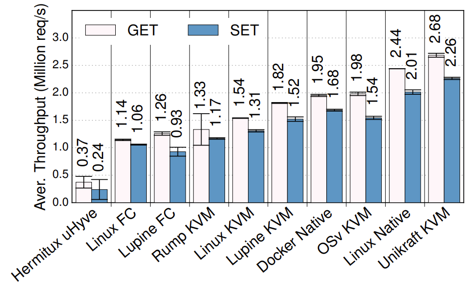
Redis throughput under various setups (higher is better)
This graph is taken from the Unikraft paper:
S. Kuenzer et al., Unikraft: Fast, Specialized Unikernels the Easy Way, EuroSys’21
The graph shows the throughput for Redis, which is a very popular key value store, in millions of requests per second. There are various setups on the X axis including different unikernels, as well as vanilla Linux. As you can see Unikraft is the fastest solution: even if it runs virtualised on top of Qemu/KVM, it is still a bit faster than Linux non-virtualised, and also much faster than Linux in a VM. Feel free to check out the paper for more performance evaluation.
Given these benefits unikernels have plenty of application domains. We motivated them with cloud environments such as server or microservice software. But they have also been explored in the domains of embedded virtualisation, edge computing and IoT. Network function virtualisation, high performance computing, and various security critical domains such as VM introspection, malware analysis, and secure desktop environments. Still an important point to note is that most unikernels are still at the stage of research prototype. This is different from containers which as you may know are a production-ready technology.
Unikernel Projects
A few examples of unikernel projects are listed below. Some of these are relatively unstable and poorly maintained academic research artefacts. The most mature project, the one that is the closest to production ready status, is Unikraft.
Unikernels can be classified based on the targeted language for supported applications:
- Pure memory safe languages (OCamL, Erlang, Haskell): MirageOS, LING, HalVM
- C/C++, semi-posix API: Unikraft, HermiTux, HermitCore, OSv, Rumprun, Lupine
- Rust/Go: Hermit, Clive
- More: https://unikernelalliance.org/projects/
Compatibility Aspects
Although they present desirable security and lightweightness benefits, unikernels also suffer from an important drawback which stems from their custom OS nature: a lack of compatibility with existing software and, to a lesser extent, hardware. On the hardware side, it is not possible for unikernel project to integrate the large amount of drivers supported by popular OSes such as Windows or Linux. Still, using the split driver model (frontend/backend) driver model we saw that is common in virtualised environments, a unikernel supporting popular paravirtualised (e.g. Virtio) I/O frontend drivers and running alongside e.g., Linux, will be compatible with numerous I/O devices. The real compatibility problem of unikernels rather lies on the software side.
One of the reasons unikernels are not particularly popular today, despite being around for more than a decade now, is that it is hard to run existing application on top of them. Most unikernels require access to an application’s source to compile it with the unikernel OS, so in scenario where the sources are not available for a given application (e.g., proprietary software), a unikernel cannot be created. Even when sources are available, as we’ve seen previously, most unikernel model support only one or a few programming languages, which limits compatibility.
Many applications will also require specific OS features available under e.g., Linux or Windows, but unsupported by most unikernel models. Porting is thus required: one can try to adapt an application to work on top of a unikernel model, or to enhance the unikernel model for it to provide the features required by the application. Often, porting involves doing a bit of both: it is time-consuming task which requires expertise in both the application to be ported, and the unikernel model to use, which discourages many prospective users.
Since that problem was identified, several research efforts attempted to enhance the compatibility issues of unikernels. The main idea is to require as little modifications/effort as possible to execute as a unikernel an application that already builds for and runs on top of a popular OS such as Linux. The compatibility can be achieved at various levels, from the weakest to the strongest:
- Source-level compatible unikernels (e.g., HermitCore, Rumprun): these require to recompile an application’s code with a custom C standard library and the unikernel kernel. It is a relatively weak form of compatibility, as the C standard library is not the only interface with the kernel in many applications. This approach also still requires recompilation and access to the sources.
- C standard library-level binary-compatible unikernel (e.g., OSv, Lupine): these interface an application at runtime with a custom C standard library, similarly to how shared libraries are loaded at runtime. These approaches may sometimes avoid recompilation, but are still limited to programs requesting OS services only through the C standard library.
- System call-level binary compatible unikernels (e.g., HermiTux, Unikraft): this is the strongest form of compatibility targeting the standard app/OS interface: the unikernel OS hooks into the system calls made by an application compiled for a popular OS (e.g., Linux) and emulates that OS behaviour. Such compatibility at the system call level allows running unmodified Linux application as unikernel without access to the sources/recompiling.
For more information on the topic of unikernels and application compatibility check out this paper:
Olivier et al., A Binary-Compatible Unikernel, VEE’19
Lab Exercise
The lab exercise can be accessed here.