Background: I/O Device Access in Computer Systems
Here we briefly present how an OS communicates with I/O devices.
Overview
There are three ways for the OS and devices to interact:
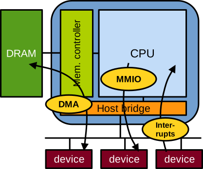
Memory-mapped I/O (MMIO) maps device registers into the OS address space, so reading/writing those addresses reads/writes the device’s registers directly. It is unidirectional (OS to device) and limited to small, register-sized messages. For example, the OS enables networking on a network card through MMIO.
Interrupts are unidirectional notification signals sent from the device to the OS; they carry no data. For example, a network card raises an interrupt to tell the OS a packet has arrived and should be fetched.
Direct memory access (DMA) is bidirectional and transfers large quantities of data between memory and the device. With our network card example, sending/receiving network packets between the host and the device is done through DMA. DMA transfers use ring buffers in memory (producer-consumer channels): the OS uses MMIO to give the device the ring buffer’s base address, length, and head/tail pointer locations, and MMIO/interrupts then coordinate the transfers.
In this exercise we will write drivers for devices using MMIO and interrupts only (no DMA).
Memory-Mapped I/O
An I/O device exposes a series of registers, each with a specific size (e.g., 32 bits) and access mode (read-only, write-only, or read-write), that the OS reads and writes with MMIO. For example, a network card may expose:
- A read-only STATUS register encoding its current state: transmitting/receiving, idle, etc.
- A write-only COMMAND register for the OS to trigger actions: send a packet, reset the device, etc.
- A read-write CONTROL register for configuring the device and reading back its configuration.
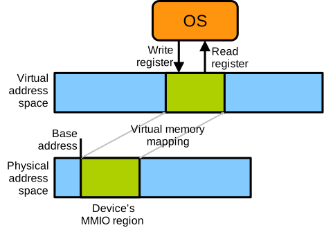
At boot time, the motherboard firmware (BIOS/UEFI) configures the hardware so that CPU LOAD/STORE instructions at certain addresses are directed to devices’ registers. Each device is thus assigned a contiguous area of the physical address space, its MMIO area, for the OS to read and write its registers. The physical address of that area’s first byte, its base address, is stored in a PCI configuration-space register called the Base Address Register (BAR). Each register the device exposes is identified by a specific offset from that base address. For a real-world example, see page 447 of the Intel 82576EB Ethernet controller datasheet, which lists exposed registers with their BAR offset, name, and access mode.
Once virtual memory is enabled at boot time, LOAD/STORE instructions can only target virtual addresses. The OS therefore maps each device’s MMIO area into its own virtual address space, after which it accesses the device’s registers by reading/writing that virtual memory area, as illustrated below:
In the development environment you should have up and running, you can list the PCI devices attached to the VM and see their physical base address as follows:
alpine:~# lspci -v
# ...
00:01.0 Unclassified device [00ff]: Device 1234:cafe (rev 03)
	Subsystem: Red Hat, Inc. Device 1100
	Flags: fast devsel
	Memory at febd0000 (32-bit, non-prefetchable) [size=4K]
	Kernel driver in use: edu_rng_sync

00:02.0 Unclassified device [00ff]: Device 1234:f00d (rev 10)
	Subsystem: Red Hat, Inc. Device 1100
	Flags: fast devsel, IRQ 10
	Memory at febd1000 (32-bit, non-prefetchable) [size=4K]

00:03.0 Unclassified device [00ff]: Device 1234:beef (rev 01)
	Subsystem: Red Hat, Inc. Device 1100
	Flags: fast devsel, IRQ 11
	Memory at feb80000 (32-bit, non-prefetchable) [size=128K]
# ...
The physical base address for each device follows Memory at and is given in hexadecimal.
Interrupts
Interrupts let a device notify the OS when relevant events occur, and are sent from the device to the CPU. At boot time, the CPU is configured to jump, for each interrupt type, to a predefined piece of OS code upon reception: this is called an interrupt handler. Handlers exist because interrupts are asynchronous: the CPU is generally busy (running an application or the OS) when one arrives. On reception, the context (CPU register values) of whatever was running) is saved to memory, and the CPU jumps to the handler. The handler reacts to the interrupt, e.g., fetching a packet the network card has signalled as received, then acknowledges it to the device and restores the saved context, so that application and OS code are interrupted transparently.
Assume a hypothetical scenario in which an application regularly prints messages to the console, and an OS has installed the following interrupt handler:
// OS code, interrupt handler:
void interrupt_handler() {
    printk("interrupt received!\n");    // printk is the kernel's equivalent of printf
    /* handle the interrupt ... */
    ack_interrupt();
    return;
}

// application code running at the time the interrupt is received:
void app_code() {
    for(int i=0; i<10000; i++) {
        printf("iteration %d ...\n", i);
        sleep(1);
    }
}
If the interrupt is received while the application runs, we may see the following:
# ...
iteration 42
iteration 43
iteration 44
interrupt received!
iteration 45
iteration 46
# ...
Handling an interrupt generally involves MMIO or DMA with the device, e.g. to check the reason for the interrupt or retrieve data. In the Intel Ethernet controller datasheet, the interrupt reason is encoded in the ICR MMIO register (page 504).