CPU & Memory Virtualisation
You can access the slides 🖼️ for this lecture.
Introduction
We have seen that x86-32, among other ISAs, was not virtualisable based on the Popek and Goldberg theorem. And that attempts at virtualising it had to compromise on performance or equivalence. Due to the high demand for virtualisation in the early 2000s, and the related problems with x86-32, the next-generation ISA, x86-64 (first proposed in the early 2000s), did not make the same mistake. x86-64 was designed with hardware-based virtualisation support in mind. This is achieved with Intel processors using three key technologies: VT-x for CPU virtualisation, Extended Page Tables (EPT) for memory virtualisation, and VT-d for I/O virtualisation. We will focus on Intel here, but note that AMD, a manufacturer of x86-64 CPUs, has very similar technologies.
x86-64 CPU Virtualisation with VT-x
Motivation
Let us start with CPU virtualisation. The existing software techniques used to virtualise x86-32 had the following challenges. First, the guest OS runs in a privilege level it was not designed for, namely user mode. With x86, privilege levels are called rings. Supervisor mode is ring 0 and user mode is ring 3. Yet we have guest OSes running in ring 3 for virtualisation, whereas they were designed to run in ring 0. Second, the hypervisor needs to be located somewhere in memory and be inaccessible from the guests. Third, the performance impact of the traps, necessary to emulate every sensitive operation, is significant. The traps representing guest-host transitions are frequent and costly, leading to significant performance slowdowns.
The key design idea behind VT-x, x86-64’s hardware support for CPU virtualisation, was to propose a holistic solution rather than addressing each issue with x86-32 separately.
For example, changing the semantics of individual instructions such as POPF would be detrimental to backward compatibility.
The x86-64 designers instead addressed all issues by introducing a new mode of execution.
The entire CPU state is duplicated into two modes: root mode for running the hypervisor and host operating system code, and non-root mode for virtual machine code.
VT-x Overview
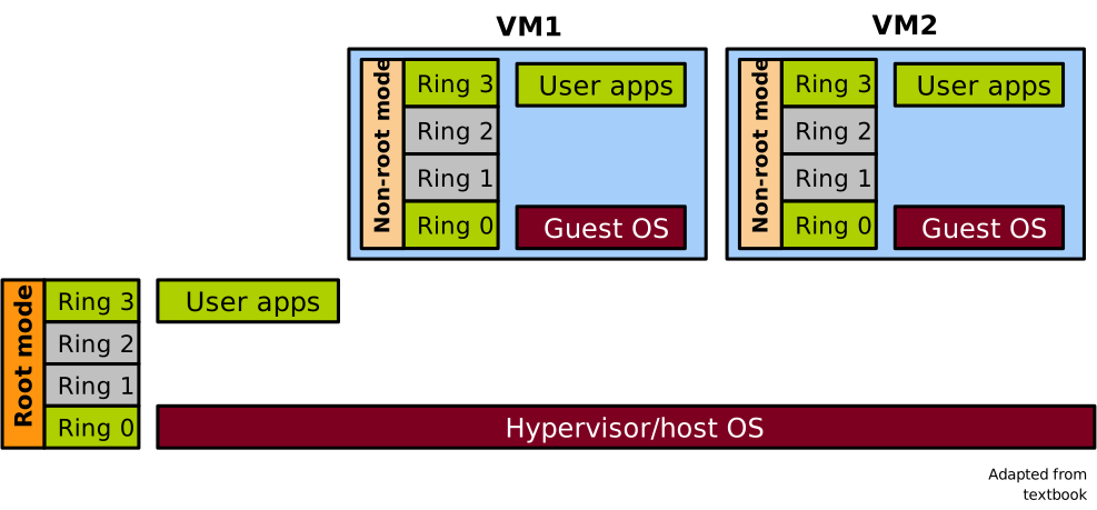
The two modes are illustrated here: a diagram showing a machine with one hypervisor and host OS running in root mode at ring 0, and host-level applications running in root mode at ring 3. We also have two VMs, each running a guest OS in non-root mode in ring 0, and guest applications in non-root mode in ring 3.
At any point in time the CPU is either in root or non-root mode, and privilege levels (rings) are orthogonal to the root/non-root modes and are available in both. Each mode has its own address space, which is switched automatically upon transitions, including virtual memory translation caches. This allows the hypervisor and other host-level software to be well isolated from the guest software.
VT-x and P&G
Remember the key objectives for a proper hypervisor that we listed in the previous lecture. In terms of equivalence, the state of the virtualised CPU exposed by VT-x in non-root mode to VMs is an exact duplicate of the physical CPU state: guests can run x86-64 code and are also backward compatible with x86-32. Regarding safety, with architectural support the hypervisor codebase is much simpler, which leads to a reduced attack surface compared to approaches based on emulating the execution of the entire guest OS or on paravirtualisation, which need to maintain complex invariants. Finally, concerning performance, it was not a primary goal at first: the first generation VT-x CPUs were actually slower than state-of-the-art paravirtualised/OS emulation approaches.
With the root and non-root modes introduced in x86-64, we can rework the Popek and Goldberg theorem as follows:
When executed in non-root mode, all sensitive instructions must either 1) cause a trap or 2) be implemented by the CPU and operate on the non-root duplicate of the CPU state
If each sensitive instruction traps to the VMM in root mode, it would satisfy the equivalence and safety criteria. However, these traps are very costly, and we cannot have them be too frequent. Ideally we want as few traps as possible to keep performance close to native execution. Clearly, managing the virtualisation of more privileged instructions in hardware means implementing more logic in the CPU, so there is a trade-off between hardware complexity and cost versus performance here.
Root/Non-Root Transitions
Let us briefly see how VT-x manages transitions between root and non-root modes.
Assume the hypervisor is initially running in root mode.
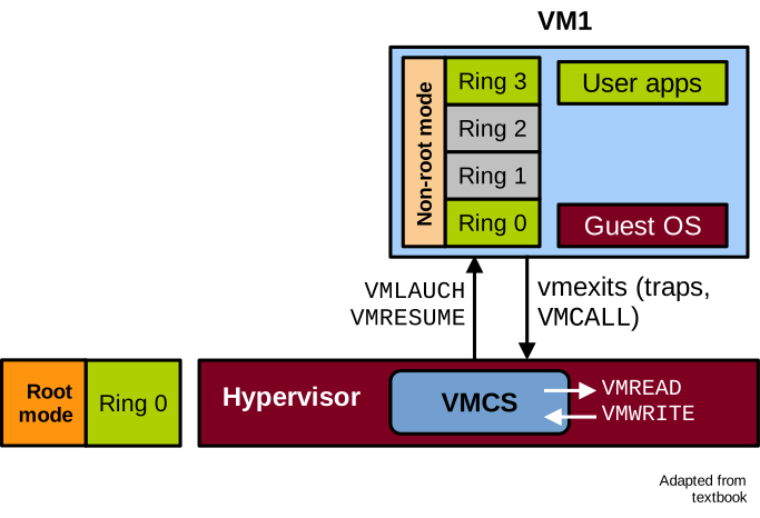
The hypervisor can start and resume a VM with the VMLAUNCH and VMRESUME instructions.
This causes the CPU to switch to non-root mode and start running the guest.
Conversely, transitions from the VM to the hypervisor are called VM exits.
The VM will transition to the hypervisor following a trap or an explicit call to switch to the hypervisor via the VMCALL instruction.
In these cases the CPU switches from non-root to root mode and starts running hypervisor code to handle the trap.
When a VM exit occurs, the CPU maintains a data structure containing information about the guest, such as the reason for the VM exit.
This is called the Virtual Machine Control Structure (VMCS).
The hypervisor must use specific instructions to access it: VMREAD and VMWRITE.
These operations and the VMCS can be illustrated as follows:
The list of categories of VM exit reasons follows:
| Category | Description |
|---|---|
| Exception | Guest instruction caused an exception (e.g. division by 0) |
| Interrupt | Interrupt from I/O device received during guest execution |
| Triple fault | Guest triple faulted |
| Root-mode sensitive | x86 privileged/sensitive instructions |
| Hypercall | Explicit call to hypervisor through VMCALL |
| I/O | x86 I/O instructions, e.g. IN/OUT |
| EPT | Memory virtualisation violations/misconfigurations |
| Legacy emulation | Instruction not implemented in non-root mode |
| VT-x new | ISA extension to control non-root execution (VMRESUME, etc.) |
VM exits occur when the CPU faults or invokes a system call (software exceptions), when an interrupt is received from an I/O device, when the guest encounters a triple fault, or when it invokes a sensitive instruction. The guest can also voluntarily trigger a VM exit, which is called a hypercall. The hypercall is to a hypervisor what a system call is to an operating system. Other categories include I/O instructions, memory virtualisation VM exits, instructions that need to be emulated, and VT-x instructions themselves.
Introduction to KVM
KVM is a hypervisor integrated into the Linux kernel and leveraging VT-x on x86-64. KVM stands for Kernel-based Virtual Machine. It is a type 2 hypervisor designed within Linux from the ground up assuming hardware support for virtualisation, like VT-x for x86-64 and equivalent technologies for the other modern ISAs.
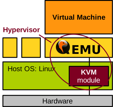
KVM is a module in the Linux kernel code, so it lives in kernel space. KVM partially manages virtual machines by handling traps, maintaining the Virtual Machine Control Structure (VMCS), and so on. Still, KVM must also rely on a user-space program to handle other virtual machine management tasks, in particular resource allocation. That user-space program is very often QEMU. QEMU was originally a machine emulator, but CPU and memory emulation can be disabled when running on top of KVM, because they are managed by VT-x and the memory virtualisation technology we will cover shortly: this makes things much faster, close to native performance. The KVM + QEMU combination is arguably the most popular hypervisor today.
x86-64 MMU Virtualisation with EPT
We have covered the CPU; let us now discuss hardware-assisted memory virtualisation for x86-64. The first iterations of x86-64 did not have support for hardware-assisted memory virtualisation, only VT-x for the CPU. They assumed disjoint page tables for root and non-root modes, which was efficient to isolate the hypervisor from the guest by making sure they could not map each other. However, every guest page table update still needed to trap to the hypervisor to be validated, to make sure the guest does not try to map something it should not have access to. This is called shadow paging, and it is notoriously slow because page table updates are quite frequent.
Without hardware support for MMU virtualisation, another option is paravirtualisation, i.e., to modify the guest so that it does not update page tables directly, but rather requests the hypervisor to do so in a controlled fashion. As we saw, paravirtualisation breaks equivalence, so this solution is not ideal either.
Extended Page Tables: Introduction
There was a need for hardware support for memory virtualisation, similar to what VT-x does for the CPU. The technology for memory virtualisation is called Extended Page Tables and was presented in this seminal paper in 2008:
R. Bhargava et al., Accelerating Two-Dimensional Page Walks for Virtualised Systems, ASPLOS’08
With EPT the guest OS maintains its page tables normally. It can update them freely without traps to the hypervisor. There is one page table per guest process, and it maps guest virtual to guest pseudo-physical addresses. The key idea behind EPT is to add a second level of address translation, the extended page table. There is one extended page table per VM, and it maps guest pseudo-physical addresses to host physical addresses:
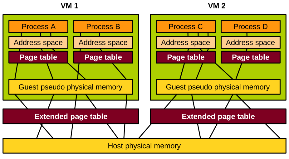
The hypervisor is in total control of these extended page tables, hence it can ensure that guest OSes map only the memory they are allowed to access.
With performance in mind, having to walk 2 levels of page table is concerning. Still, EPT is designed such that the translation caches, i.e. Translation Lookaside Buffers (TLBs), will cache the guest virtual to host physical mapping directly. Knowing that the TLB hit rate is about 95% in modern CPUs, there is no need to walk two levels of page tables for the majority of VM memory accesses. However, if there is a TLB miss, then these two levels must be walked: the guest’s page table, and the extended page table.
EPT Walk
Before explaining the EPT walk, let us see how the MMU walks a traditional (non-virtualised) page table to perform address translation on a memory access.
The page table is rooted in the %cr3 register.
Different parts of the target virtual address will index each level of the page table
until the target data page is found.
An offset from the beginning of that page, derived from the least significant bits of the address, is added to find the target byte to load or store.
This is illustrated here:
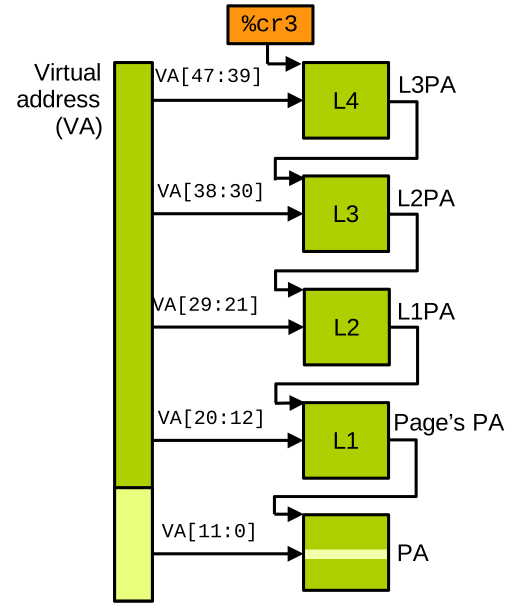
On the left is the virtual address the CPU wants to access, and on the right is the page table. The goal of the page table walk is to find the physical address corresponding to the virtual one, in order to perform the memory access.
The %cr3 register contains the physical address of a page constituting the root of the page table.
On standard CPUs page tables are a tree with 4 levels, and the root is the 4th level.
That address contains 512 64-bit entries, each of which is a pointer to a page in the next (3rd) level of the page table.
The root of the page table is indexed by bits 39 to 47 of the virtual address the CPU wants to access (note that most modern CPUs do not use the full 64 bits of a virtual address, but rather 48).
This selects an entry in the root page, indicating which 3rd level page to use next.
The bits 30 to 38 of the address are used to index that page, giving us the 2nd level page, indexed with bits 21 to 29, giving us the 1st level page, indexed with bits 12 to 20.
The 1st level page table entry points to the page containing the physical address we need, and that page is finally indexed with bits 0 to 11 to find the target byte.
When running virtualised, address translation must walk both the guest page table and the extended page table. Things work as follows:
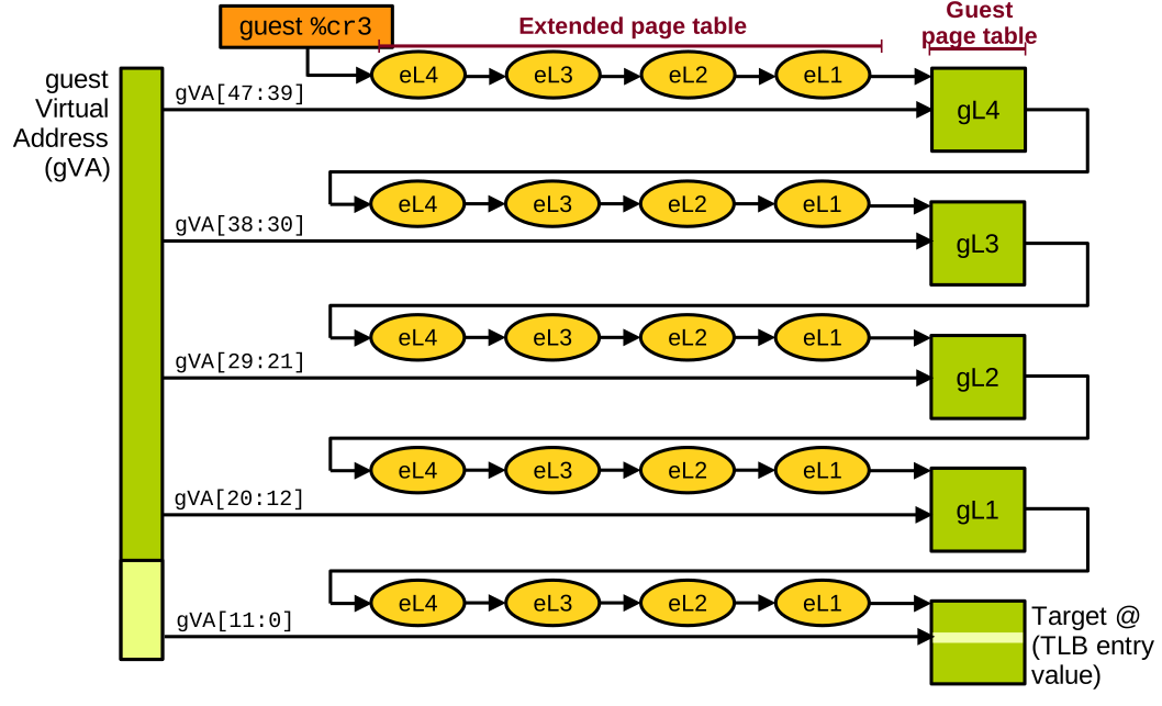
We have the virtual address targeted by the guest on the left.
The guest page table is rooted in %cr3.
It contains a guest pseudo-physical address, so we first need to translate it into a host physical address.
We therefore walk the extended page table to figure out which physical page contains the root of the page table, which is level 4.
Once found, it can be indexed with the most significant bits (bits 39 to 47) of the target address, which gives us the address of the next-level page (3rd level).
However, that address is a guest pseudo-physical address, and we need to similarly translate it into a host physical one, so we walk the extended page table again.
This process repeats to find the 2nd level page, the 1st level page, and finally the target data page, which can be indexed by the least significant bits (0 to 11) of the target guest virtual address to find the byte the guest wants to load or store.
In the end, to walk the 2D page table, we had to do 24 memory accesses to load or store a single byte. By comparison, only 4 memory accesses are needed to walk a standard page table when running non-virtualised. That is a very high overhead, but remember that 95% of guest memory accesses do not need to go through this, as they hit in the translation cache (the TLB – Translation Lookaside Buffer).
Memory Virtualisation in KVM
KVM of course makes use of extended page tables to manage the VMs’ memory. Address translation works as follows:
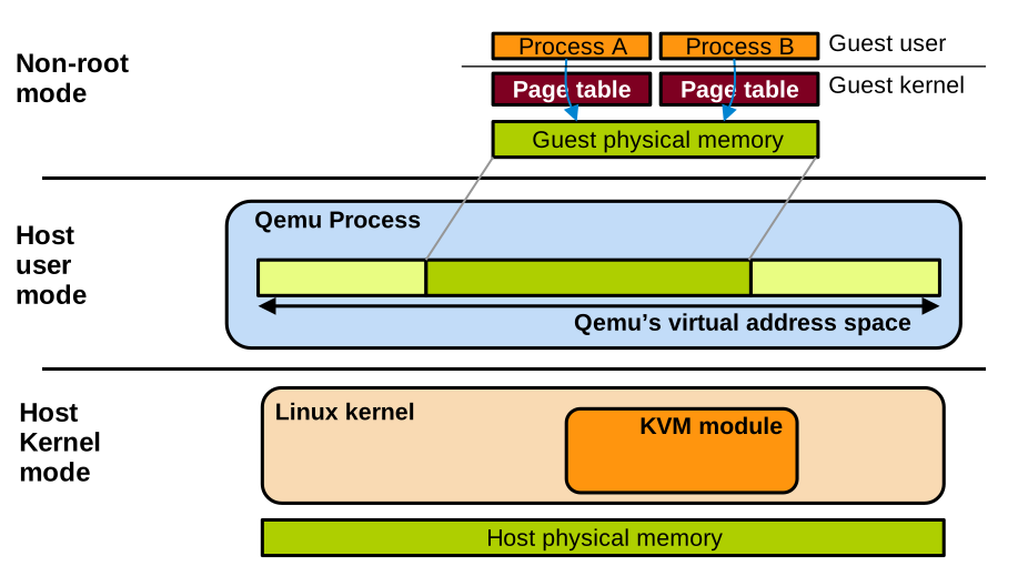
The guest manages its own page tables, one per guest process, with minimal intervention from KVM.
QEMU lives in the host user space as a regular process.
Like every other process, it has its own virtual address space.
QEMU makes a large call to malloc to allocate a large contiguous buffer that will be the guest’s pseudo-physical memory.
The KVM module lives in the host kernel. It sets up and manages the extended page tables that map the guest pseudo-physical addresses to host physical memory.
Sometimes the QEMU process needs to read and write the VM’s memory too, for example when virtualising I/O as we will see next. For this, it can read and write in that large area of virtual memory it allocated for the VM, and the page tables of QEMU on the host will be used for the translation, as with any other host process.